That demand is reshaping the supply chain. The automotive PCB market hit $9.8 billion in 2023 and is projected to reach $14.1 billion by 2030, based on Grand View Research's automotive PCB market report.
What separates an automotive PCB from a standard board? Vibration resistance, extreme temperature tolerance, moisture protection, and compliance with safety standards that consumer electronics never touch. A single design flaw here doesn't just mean a returned product. It can trigger a recall, a failed safety certification, or a stalled vehicle program.
This guide covers the board types, design challenges, engineering practices, standards, and cost factors that matter most for automotive PCB programs, plus how working with a single-source manufacturing partner reduces risk along the way.
Key Takeaways
- Automotive PCBs must withstand vibration, heat, and EMI while meeting IATF 16949 and IPC-6012
- Match board type (rigid, flex, metal-core, HDI) to actual thermal and space needs
- The 3W rule and proper grounding cut crosstalk risk in dense automotive layouts
- Coating and moisture failures have caused recalls affecting nearly 14,000 vehicles
- A single-source manufacturing partner cuts NPI time and ends vendor finger-pointing
Types of Automotive PCBs Used in Vehicles
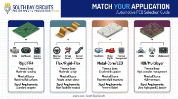
Not every automotive circuit board faces the same stress. A board mounted rigidly under the hood has different needs than one flexing inside a steering column. Matching board type to application is the first design decision that determines long-term reliability.
Rigid PCBs (FR4)
Standard FR4 rigid boards remain the workhorse for stationary automotive electronics. They show up in:
- Engine control units (ECUs)
- Dashboard clusters and instrument panels
- Rear-view camera modules
These applications need mechanical stability more than flexibility, and FR4 delivers that at a manageable cost.
Flexible and Rigid-Flex PCBs
Tight, moving, or 3D-mounted spaces call for a different construction. Flex and rigid-flex boards bend around corners and absorb vibration without cracking. Common use cases include:
- Steering column electronics
- Airbag sensor assemblies
- Lighting harnesses that route through curved body panels
Metal-Core and LED PCBs
High-brightness LEDs generate heat that FR4 alone can't dissipate fast enough. Metal-core boards, including flex-on-aluminum constructions, solve this. Engineering data on these builds consistently points to flex-on-aluminum designs for front headlight assemblies, where thermal management and mechanical durability both matter. The same logic applies to brake lights and turn indicators.
Multilayer, HDI, and High-Frequency PCBs
ADAS, radar, and infotainment systems need dense routing and clean signal integrity. This is where high-layer-count, HDI, and hybrid-material boards earn their place, supporting the impedance control and via-in-pad technology that radar and LiDAR systems demand. A 77 GHz radar module, for example, routes dozens of high-speed differential pairs through a board smaller than a smartphone, leaving zero margin for impedance mismatch.
The takeaway: pick the board type based on thermal load, physical space, and signal requirements. Defaulting to the most advanced (and expensive) option for every application wastes budget without improving reliability.
Top Design Challenges in Automotive PCB Development
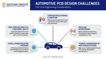
Automotive PCBs operate in one of the harshest environments any electronic component will see. Engineers face five recurring challenges.
Temperature Extremes and Vibration
Automotive-grade ICs are qualified under AEC-Q100, which defines four temperature grades based on where the board sits in the vehicle.
| Grade | Temperature Range | Typical Location |
|---|---|---|
| 0 | -40°C to +150°C | Engine bay, exhaust-adjacent |
| 1 | -40°C to +125°C | Under-hood, transmission |
| 2 | -40°C to +105°C | Cabin, dashboard electronics |
| 3 | -40°C to +85°C | Infotainment, comfort systems |
A board mounted near an engine or exhaust system needs Grade 0 or 1 components, while a cabin-mounted infotainment unit may only need Grade 2 or 3. Vibration adds a second layer of stress: boards must survive years of road-induced shock without cracked solder joints or fatigued traces.
EMI and EMC Interference
Radar, cameras, and wireless modules are packed closer together than ever. Without adequate shielding, this density creates real risk: sensor errors, false radar targets, or outright ADAS malfunction. Inadequate isolation between a radar module and adjacent digital circuits can raise the noise floor enough to mask genuine obstacles or invent phantom ones.
Thermal Management in High-Power Systems
EV inverters, onboard chargers, and battery management systems push more current through smaller footprints than traditional automotive electronics ever did. Inadequate heat dissipation here doesn't just shorten component life. It can cause outright failure.
This isn't theoretical. NHTSA recall 25V-125, filed in early 2025, covers 13,769 vehicles (Volkswagen ID.4 and Audi Q4 e-tron models) after condensation combined with insufficient PCB protective coating caused electromigration in an onboard charger's DC-DC converter.
The result: loss of 12V charging and potential loss of motive power. Full details are documented in NHTSA's safety recall report 25V-125.
That single case illustrates why coating coverage and moisture protection aren't optional line items on a spec sheet.
Space and Miniaturization Pressure
Vehicles keep adding electronics without adding room. This pushes designers toward HDI and rigid-flex constructions that pack more function into less board area, especially in zonal architectures where multiple ECUs consolidate into shared modules.
Long-Term Reliability and Functional Safety
Braking, steering, and other safety-critical systems fall under ISO 26262, the functional safety standard for road-vehicle electronics. The stakes go beyond a field failure. Non-compliance can delay vehicle certification entirely, pushing back a program's launch date by months.
Essential Automotive PCB Design Guidelines
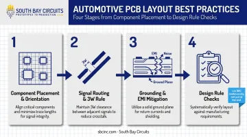
Meeting automotive reliability standards comes down to disciplined layout practices. Here's the practical playbook.
Component Placement and Orientation
Smart placement prevents problems before they start:
- Group similar components together to simplify soldering processes
- Orient parts consistently with wave soldering direction to avoid shadowing
- Separate analog and digital sections to reduce noise coupling
- Space high-power components away from sensitive circuits to manage heat and prevent interference
Getting this wrong doesn't always show up in initial testing. It shows up six months into field deployment when thermal cycling exposes a marginal placement decision. A connector positioned too close to a heat sink, for example, can pass initial bench tests yet fail vibration testing once installed in the vehicle's engine bay.
Signal Routing and the 3W Rule
The 3W rule is a foundational crosstalk-prevention guideline: keep trace-to-trace spacing at least three times the trace width. In space-constrained automotive layouts, where every millimeter is contested, this rule matters more than in a spacious consumer product design.
Skip it, and you risk signal coupling between adjacent lines that can corrupt sensor data or communication signals.
Some automotive applications push this further. High-speed automotive Ethernet interfaces often call for even wider separation, closer to 5W, between multiple interface pairs to maintain signal integrity.
Additional routing practices worth building into every layout:
- Place power and ground planes on inner layers for consistent reference
- Use differential pairs for high-speed signals, maintaining controlled impedance
- Minimize via count on high-current paths to reduce inductance and resistance
Grounding and EMI Mitigation
Clean grounding is the backbone of EMI control. Best practices include:
- Single-point grounding to prevent ground loops
- Continuous, low-impedance ground planes rather than fragmented copper pours
- Decoupling capacitors placed as close as possible to IC supply pins
A single ground loop introduced by a fragmented copper pour, for instance, can inject enough noise to trigger a false CAN bus fault code during cold-start testing.
Running frequent design rule checks (DRC) throughout the layout process, not just at the end, catches spacing, grounding, and connectivity errors before they reach fabrication. Catching an error on screen costs minutes. Catching it after tooling is cut costs weeks.
Automotive PCB Standards and Certifications to Know
Automotive PCB programs touch four distinct standards, each governing a different piece of the process.
| Standard | What It Covers | Who It Applies To |
|---|---|---|
| IPC-6012 Class 3 | Annular ring size, plating thickness, hole tolerances for high-reliability boards | PCB fabricators |
| AEC-Q100 | Stress-test qualification for automotive-grade ICs | Component/IC suppliers |
| IATF 16949 | Quality management system across design, fabrication, and assembly | Manufacturers |
| ISO 26262 | Functional safety lifecycle for safety-critical E/E systems | System-level vehicle electronics |
IPC-6012 Class 3 sets the baseline acceptance criteria for high-reliability automotive boards, covering everything from copper plating thickness to hole tolerance. AEC-Q100 qualifies the ICs themselves against automotive stress conditions, not the board they sit on.
IATF 16949 is the quality management standard that manufacturers must follow to demonstrate process consistency. South Bay Circuits is ISO TS 16949 Automotive Compliant, so process discipline carries through design, fabrication, and assembly instead of breaking down at a handoff between vendors.
ISO 26262 sits above all of this at the vehicle system level, governing functional safety for braking, steering, and other safety-critical electronics. A board can pass every fabrication spec and still fail a program if the system-level safety case isn't built correctly around it.
How Much Does Custom Automotive PCB Design Cost?
Automotive PCB costs vary widely, but the drivers are consistent across programs.
Primary Cost Drivers
- Layer count and stack-up complexity: more layers mean more process steps and tighter registration requirements
- Material selection: standard FR4 costs less than high-temperature laminates like polyimide or Rogers materials needed for radar and high-frequency applications
- Layout complexity and tolerances: tight impedance control and fine-pitch routing add engineering time
Design decisions made early in the cycle determine the majority of downstream manufacturing cost, according to I-Connect007's coverage of PCB design cost drivers. Locking in stack-up and material choices before layout begins avoids expensive rework later.
Volume and Testing Add-Ons
Batch size matters. Prototype and low-volume runs carry higher non-recurring engineering (NRE) costs since tooling and setup expenses spread across fewer boards. Production volume brings per-unit costs down significantly.
Testing isn't optional for safety-critical boards, and it isn't free either:
- Runs thermal cycling and thermal shock tests to confirm performance across temperature extremes
- Conducts vibration testing to simulate real-world road conditions
- Uses X-ray inspection to catch hidden solder joint and BGA defects
These validation steps add cost, but skipping them on a safety-critical board is a false economy. Ask any team that's issued a recall.
Why a Single-Source Model Controls Cost
Splitting design, fabrication, and assembly across separate vendors introduces queue time, shipping delays, and finger-pointing when a defect shows up. South Bay Circuits handles design through fabrication and assembly under one roof in its Chandler, Arizona facility, which cuts NPI time and removes the handoff gaps that stretch out automotive program timelines.
That in-house model, combined with fast turnaround capabilities like 24-hour fabrication and same-day assembly, gives automotive programs a real edge. When a design revision needs to move from layout to loaded board, there's no waiting in someone else's queue.

Frequently Asked Questions
What is an automotive PCB?
An automotive PCB is a circuit board engineered specifically for vehicle electronics. It's built to withstand vibration, temperature extremes, and EMI while meeting standards like IATF 16949 and IPC-6012.
How much does a custom automotive PCB design cost?
Cost depends on layer count, material selection, production volume, and testing requirements. Working with a single-source manufacturer typically reduces total program cost by eliminating vendor handoffs and NRE duplication.
What is the 3W rule in PCB design?
The 3W rule requires trace-to-trace spacing of at least three times the trace width to reduce crosstalk. It's especially important in dense automotive layouts where board space is limited.
What certifications should an automotive PCB manufacturer have?
Look for IATF 16949 (quality management), ISO 9001 (general quality systems), and evidence that components meet AEC-Q100 qualification. Together, these indicate genuine automotive-grade capability.
How many PCBs are typically found in a modern vehicle?
Some premium vehicles now contain 150 or more ECUs, each requiring its own circuit board, according to McKinsey's research on vehicle E/E architecture. That number continues climbing as ADAS and electrification features expand.
What's the difference between rigid and rigid-flex PCBs for automotive use?
Rigid boards suit stable mounting locations like ECUs and dashboard modules. Rigid-flex suits tight, moving, or 3D-mounted spaces such as steering columns and lighting assemblies where the board needs to bend without cracking.