Many engineers coming from commercial or industrial electronics struggle with this shift. Standard FR-4, generic surface finishes, and commercial-tolerance components simply don't survive the temperature swings, constant vibration, and 20+ year service life that defense programs demand. A board qualified for a consumer product might fail after a few thousand thermal cycles; a military board often needs to survive tens of thousands.
This guide walks through the MIL-SPEC standards that govern military PCBs, the materials and design rules that keep them alive in harsh environments, and how to vet a manufacturing partner capable of delivering all of it without missing a deadline.
Key Takeaways
- Qualify boards to MIL-PRF-31032, MIL-PRF-55110/50884, and IPC-A-610/J-STD-001
- Choose high-Tg laminates, polyimide, ENIG, or immersion silver for thermal reliability
- Design for vibration, shock, thermal loads, and EMI/EMC as core defense requirements
- Catch weak boards early with ESS plus thermal and vibration testing
- Cut handoff risk and timelines with an ITAR-registered, AS 9100 single-source partner
Military PCB Standards & Certifications You Must Know
Defense electronics compliance isn't one certificate covering everything. It's a stack of separate mechanisms, each governing a different layer: process qualification, board construction, assembly workmanship, and organizational security.
MIL-PRF-31032 is the Defense Logistics Agency's current qualification framework for rigid, flex, and rigid-flex boards. Rather than defining one fixed construction spec, it establishes the Qualified Manufacturers List (QML) process that a fabricator's quality system and production flow must pass before technologies get listed.
Certification comes first, then technology-specific qualification testing follows.
Two legacy standards still show up on older programs:
- MIL-PRF-55110 covered rigid single-, double-, and multilayer boards. Inactive for new designs since 1997, but still referenced on older boards in service.
- MIL-PRF-50884 governs flexible and rigid-flex circuits where weight and space are tight. DLA has issued a cancellation notice—confirm applicability before specifying it on new programs.
On the workmanship side, two IPC documents matter most:
- IPC-A-610 sets acceptance criteria for assembled boards
- IPC J-STD-001 (with its Space and Military Addendum) governs soldering quality
Contracts should specify the exact class and addendum requirements up front, since terminology varies by program.
AS9100 layers aerospace and defense-specific controls on top of ISO 9001. It adds configuration management, counterfeit-part prevention, and production-process verification that generic quality systems don't cover.
Handling controlled defense data adds two more requirements:
- ITAR registration under 22 CFR Part 122 for any U.S. manufacturer producing defense articles, even without exporting
- CMMC compliance, with the level set by whether the work involves Federal Contract Information or Controlled Unclassified Information
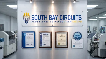
South Bay Circuits holds the credentials this stack requires:
- ISO 9001:2015 (Certificate #10000903 QM15)
- AS9100 aerospace compliance
- ITAR registration and CMMC Level 1
- IPC-6012 Class III manufacturing capability
- Boards built to meet MIL-PRF-31032 and MIL-PRF-55110 requirements
Material & Surface Finish Selection for Military-Grade PCBs
Material choice is where most reliability problems either get solved or get built in permanently. Standard FR-4 wasn't designed for the thermal punishment defense electronics endure, so the industry reaches for laminates rated to handle far more heat.
Comparing Laminate Thermal Performance
| Material | Glass Transition (Tg) | Decomposition Temp (Td) | Typical Use |
|---|---|---|---|
| Standard FR-4 (e.g., Isola DE104) | 135°C | 315°C | Commercial/industrial boards |
| High-Tg FR-4 (e.g., Isola 370HR) | 180°C | 340°C | Extended-temperature military designs |
| Polyimide (e.g., Isola P95/P25) | 260°C | 416°C | Extreme-temperature, high-reliability boards |
| Rogers 4350B / PTFE laminates | Manufacturer doesn't publish standard Tg/Td | — | RF and microwave circuits |
Higher Tg and Td translate directly into resistance to via cracking and delamination during repeated thermal cycling. For military builds, SBC commonly works with high-Tg FR-4 (including 170Tg options), Rogers 3000/4000-series RF laminates, polyimide substrates, and Nelco N4000-13/N4000-7 materials.
Copper weight matters too. Power-dense military designs often need heavier copper than commercial boards to dissipate heat and carry higher current without excessive trace heating. Typical builds start near 1/2 oz/ft² and go up to 3 oz/ft² before plating, with 2 oz trace/space common on power sections.
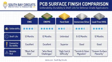
Once the laminate and copper stack are set, surface finish choice drives solderability, shelf life, and connector durability.
Surface Finish Trade-Offs
- ENIG — excellent solderability across multiple reflow cycles, more than a year of shelf life under controlled storage, but carries some black-pad and rework risk
- ENEPIG — adds palladium for improved wire-bond compatibility and corrosion resistance
- Hard gold — durable for edge connectors and repeated insertion cycles, but not readily solderable
- Immersion silver — excellent fine-pitch solderability with a 6-12 month shelf life under dry storage
- Lead-free HASL — reliable solder joints, though surface unevenness can be a concern on fine-pitch boards
Conformal coatings — acrylic, silicone, and polyurethane are the most common — protect against moisture, chemicals, and vibration-induced fatigue per IPC-CC-830.
Low CTE and low moisture absorption in the base laminate matter just as much. Both properties help prevent via cracking and delamination when boards cycle between temperature extremes.
Critical Design Guidelines for Reliability Under Extreme Conditions
Material selection sets the ceiling on reliability. Layout decisions determine whether the board actually reaches it.
Thermal management starts with heavy copper planes and thermal via arrays placed directly beneath high-power components. Separate heat-generating parts from thermally sensitive ones instead of clustering everything for routing convenience. That spacing prevents localized hot spots that shorten component life.
Vibration and shock resistance depends heavily on stack-up symmetry:
- Build balanced copper distribution across layers to prevent warping under thermal and mechanical stress
- Keep via aspect ratios conservative (many design teams target roughly 10:1 or lower) to reduce plating stress
- Avoid board geometries and mounting patterns prone to resonance under the program's expected vibration profiles
That last point matters because MIL-STD-810 doesn't impose one universal test sequence. Environments get tailored to each platform's actual service life. The design team needs the specific vibration, shock, altitude, and thermal profiles before finalizing the layout.
Signal integrity and EMI/EMC compliance rely on dedicated power and ground planes, controlled impedance routing, and shielding. MIL-STD-461 governs equipment and subsystem-level EMI verification; it does not dictate specific board-level shielding techniques. Layout decisions still determine whether the finished assembly passes those tests.
Current capacity design means keeping high-current traces short, using heavier copper where load demands it, and building in margin for unexpected spikes rather than routing to bare minimums.
For mission-critical designs, redundancy techniques such as triple modular redundancy, backup power paths, and circuit partitioning keep a single point of failure from taking down an entire system. Combined with mil-spec components at 1-2% tolerance instead of standard 5-10% commercial parts, these techniques shrink the performance variance that causes field failures years into a deployment.
Assembly & Testing Requirements for Military PCBs
Good design only pays off if the board is built and verified correctly. Assembly and test practices for defense electronics differ from commercial production at nearly every step.
Assembly Best Practices
Through-hole mounting still earns its place in high-vibration military environments because of its superior mechanical strength compared to surface mount alone. Many defense boards use a mixed-technology approach for exactly this reason.
Component sourcing carries real weight here. Counterfeit parts in the supply chain remain a persistent industry risk, which is why authorized-distributor sourcing and full traceability matter so much.
South Bay Circuits controls this through a Bill of Materials and Approved Vendor List procedure. Every BOM line item gets a part number, with manufacturer and specification data tracked through an integrated ERP system.
Soldering workmanship follows IPC J-STD-001 requirements, with inspection performed against IPC-A-610 criteria appropriate to the program's specified class.
Testing & Quality Assurance
Environmental qualification for military boards typically draws from the MIL-STD-202 and MIL-STD-810 test families, tailored to the platform's actual lifecycle rather than applied as one fixed checklist. Common candidates include:
- Thermal cycling and thermal shock
- Random and sinusoidal vibration
- Mechanical shock
- Humidity and altitude exposure
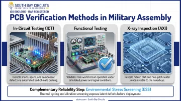
Beyond environmental testing, verification happens at the board level through:
- In-circuit testing (ICT): probes check for shorts, opens, and correct component values
- Functional testing: validates real operation, up to 100% of finished product where required
- X-ray inspection: verifies BGA solder joints and hidden connections that visual inspection can't reach
SBC applies AOI, X-ray, ICT, and functional testing across its assembly lines, alongside vibration, burn-in, and high/low temperature testing to catch weaknesses before boards ship. Environmental Stress Screening programs, guided by frameworks like MIL-HDBK-344, expose infant-mortality failures before they become field failures.
Choosing the Right Military PCB Manufacturing Partner
Certifications are the entry ticket, not the whole story. When vetting a manufacturing partner for a defense program, confirm these baseline credentials first:
- ISO 9001 certification
- AS9100 compliance
- ITAR registration
- CMMC compliance appropriate to the data being handled
Beyond paperwork, single-source capability (design, fabrication, and assembly under one roof) cuts handoff delays and closes the accountability gaps that show up when programs juggle multiple vendors. One partner owns the full build path, so issues get resolved without finger-pointing between separate shops.
Documentation matters just as much. Programs should require:
- Certificates of conformance
- Process travelers showing production history
- First article inspection reports (AS9102) confirming the initial build matches specification
South Bay Circuits has built its business around this single-source model for over 40 years. From its 60,000 sq ft Chandler, Arizona facility, the company handles PCB design, fabrication, assembly, and box builds in-house, backed by ISO 9001:2015, AS9100, ITAR, and CMMC Level 1 credentials.
That integrated model, with quick-turn paths from design through loaded assembly, keeps defense programs moving instead of stalling between vendors.
Frequently Asked Questions
What is the difference between IPC Class 3 and MIL-SPEC PCBs?
IPC Class 3 defines high-reliability workmanship acceptance criteria for assembly. MIL-SPEC certifications like MIL-PRF-31032 add DLA-governed qualification testing, documentation, and ongoing compliance requirements on top of that baseline.
Can I use commercial off-the-shelf (COTS) components in military PCB assemblies?
COTS components are increasingly accepted with proper upscreening, reliability evaluation, and documentation. Critical, high-reliability applications still typically mandate MIL-SPEC components.
What environmental testing is required for military PCB qualification?
Testing is tailored per MIL-STD-810 to the platform's lifecycle, but commonly includes thermal shock/cycling, humidity, vibration (random and sinusoidal), mechanical shock, and altitude testing.
How long does it take to qualify a manufacturer for MIL-PRF-31032?
The specification doesn't set a fixed timeline. The process includes quality-system certification, a technical review board-approved test plan, qualification-vehicle production, and testing, with duration varying by program complexity.
What certifications should a military PCB manufacturer have?
Look for ISO 9001, AS 9100 compliance, ITAR registration, and appropriate CMMC compliance as baseline credentials.
How do I ensure traceability for military PCB assemblies?
Traceability requires material certifications, component tracking against an Approved Vendor List, ERP-based process documentation, and long-term record retention across the program's service life.