Surface mount isn't one category — it's a family of component types grouped by function and package. Mixing them up on a design, or picking the wrong package for your production line, leads to real problems: tombstoned parts, thermal failures, sourcing headaches, or rework bills nobody budgeted for.
This article breaks down the main types of surface mount components, explains how they actually differ, and walks through how to choose the right ones for your design and manufacturing partner.
Key Takeaways
- Surface mount components split into three functional groups: passive, active/semiconductor, and electromechanical/interconnect.
- Package format (SOT, QFN, BGA, 0402/0603/0805) is a separate decision layered on top of component type.
- Assembly complexity, thermal behavior, and inspection needs vary far more than size alone suggests.
- Choose based on electrical requirements, production volume, and long-term reliability, not just what's newest or smallest.
What Are Surface Mount Components?
A surface mount component, or SMD (surface mount device), is any part built with flat terminations, pads, or solder balls designed to sit directly on a PCB's surface. No drilled through-holes required.
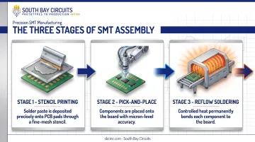
Surface Mount Technology (SMT) is the process that puts those parts there: stencil printing solder paste, pick-and-place machines positioning components, and reflow ovens melting the solder to form the joint. In short, SMD is the what; SMT is the how.
IPC guidance on surface mount assembly describes SMT as the technology that replaced older, bulkier through-hole boards with smaller, more densely populated designs. That shift shaped nearly every modern PCB in production today.
Why the Type You Pick Actually Matters
Choosing the wrong SMD type or package isn't just an aesthetic issue. It shows up later as:
- Tombstoning — small passives standing up on end during reflow due to uneven pad wetting
- Thermal failure — active components without adequate heat dissipation overheating in the field
- Sourcing shortages — non-standard packages that only one supplier stocks
- Unplanned rework — fine-pitch or leadless parts that your assembly line can't easily inspect or repair
Getting the component type and package right at the design stage avoids all four.
Types of Surface Mount Components
SMDs generally fall into three functional groups: passive, active/semiconductor, and electromechanical/interconnect. Within each group, further differences exist by package (size, lead style, thermal pad), which we'll cover separately below.
Passive Surface Mount Components
Passives (resistors, capacitors, and inductors/ferrite beads) don't amplify or switch anything. They manage resistance, capacitance, and energy storage.
Common formats include:
- Thick and thin film resistors for general resistance and precision applications
- MLCC, tantalum, and electrolytic capacitors for filtering and decoupling
- Chip inductors for current sensing and energy storage
Vishay's standard chip resistor drawings show just how much size varies: a 0402 resistor measures roughly 1.0 x 0.5mm, while an 0805 measures 2.0 x 1.25mm — a difference that matters once you're routing a dense board.
How they differ: No gain, no active control. Purely passive electrical behavior, and generally the smallest, lowest-cost packages on the board.
Best suited for: General-purpose filtering, decoupling, timing, and impedance control — used in nearly every circuit, regardless of industry.
Trade-offs: Value precision and power rating shrink along with the package. Ultra-small sizes like 0201 and 01005 are difficult to hand-place or inspect.
South Bay Circuits' Fuji-line SMT operation handles automated placement down to 0201 as a standard capability, with anything smaller subject to engineering review. That is a practical line for most production designs.
Active and Semiconductor Surface Mount Components
This group (diodes, transistors, and integrated circuits) switches, amplifies, or processes the current flowing through it.
Sub-types include:
- Schottky and ESD protection diodes
- BJTs, MOSFETs, and IGBTs for power switching
- ICs ranging from simple op-amps to high-pin-count processors in QFN, BGA, or WLCSP packages
How they differ: These parts need power and provide gain, switching, or logic functions. Unlike passives, they generate heat that has to go somewhere.
Best suited for: Power regulation, signal amplification, digital logic, RF/high-speed interfaces, and anything requiring "intelligence" on the board.
Key strengths: High-density, high-performance functionality in a small footprint. BGA packages in particular support very high I/O counts, which is why processors and FPGAs almost always ship that way.
Trade-offs: Sensitive to ESD and moisture. Hidden solder joints under QFN and BGA packages can't be checked with visual inspection alone; you need X-ray.
Texas Instruments' thermal data on its QFN logic family shows junction-to-ambient thermal impedance 48–63% lower than comparable SOIC packages, largely thanks to the exposed thermal pad. That advantage only shows up if the board design uses it.
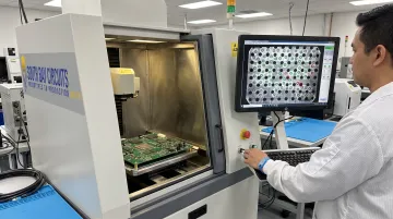
This is where inspection equipment earns its keep. South Bay Circuits uses a Glenbrook Jewel Box 70T X-ray system to verify BGA solder joints that AOI cameras can't see, paired with automated optical inspection for visible joints.
Electromechanical and Interconnect Surface Mount Components
This is the most diverse group: crystals and oscillators, connectors, switches, LEDs, and MEMS sensors. Rather than pure electrical signal processing, these parts bridge electronics with a physical, mechanical, or sensing function.
How they differ: Moving parts, mechanical interfaces, or physical transduction, not just electrical behavior.
Best suited for:
- Precise timing (crystal oscillators)
- User interaction (tactile switches, indicator LEDs)
- Sensing in IoT, wearable, or industrial monitoring applications
Key strengths: Real-world interactivity and measurement in a compact footprint. MEMS sensors and crystal packages pack a surprising amount of function into a few square millimeters.
Trade-offs: More exposed to mechanical stress, vibration fatigue, and repeated-use wear at the solder joint than purely electrical SMDs. Some connectors, particularly high-cycle or high-current types, still use through-hole mounting because it holds up better mechanically.
TE Connectivity's surface mount connector line, for instance, rates its Micro MATE-N-LOK series at up to 5A/250VAC. That rating works for many applications but still falls short of what a comparable through-hole connector can handle in high-vibration environments.
Package Size and Format: A Separate Choice
Package format (SOT-23, SOIC, QFN, BGA, or a passive size code like 0402) applies across all three component types above. It's a separate decision layered on top of function.
| Package family | Density/thermal behavior | Inspection difficulty |
|---|---|---|
| Gull-wing (SOIC, QFP) | Leads on all sides; moderate density | Easy — leads are externally visible |
| Leadless (QFN, DFN) | Compact footprint, exposed thermal pad improves heat transfer | Harder — bottom terminations need X-ray to fully verify |
| Ball-grid (BGA) | Highest I/O density via area array | Hardest — hidden balls require X-ray for shorts or voids |
South Bay Circuits' manufacturing roadmap lists 0.5mm as standard BGA pitch, 0.4mm as advanced capability, and sub-0.4mm as available for select applications. Use that as a benchmark when deciding whether your design's pitch is mainstream or pushing the envelope.
Always verify exact dimensions and thermal specs against the manufacturer's datasheet before finalizing a design. Package families vary between vendors even when the name is the same.
How to Choose the Right Type of Surface Mount Component
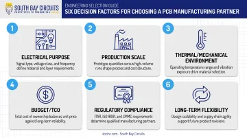
The right type-and-package combination depends on your application's electrical, mechanical, and production needs — not on what's newest or smallest. Run through these factors:
- Electrical purpose and performance — passive filtering, active switching, or RF/high-speed signal integrity all point toward different package families.
- Production scale — automated pick-and-place for volume, or hand assembly for prototypes? Validate the package on a quick-turn NPI build before you lock the BOM for production.
- Thermal and mechanical environment — vibration, temperature extremes, and expected product lifecycle are critical for automotive, aerospace, and medical applications.
- Budget and total cost of ownership — factor in component cost plus inspection and rework needs, not just unit price.
- Regulatory compliance — match process and documentation needs to the end market: ISO 13485 (medical), AS9100 (aerospace), IATF/ISO TS 16949 (automotive), and ITAR where defense applies.
- Long-term flexibility — standardized packages (0603, 0805, SOT-23, QFN) are easier to source and requalify across suppliers over the product life.
An experienced turnkey contract manufacturer can pressure-test these choices for manufacturability before you freeze the design. South Bay Circuits supports that review for aerospace, medical, automotive, and industrial OEMs—from prototype through volume—at its Chandler, Arizona facility.
Common Mistakes to Avoid
- Over-miniaturizing — choosing WLCSP or 01005 when a simpler, more serviceable package meets the actual requirement
- Ignoring rework and thermal limits until late in production, when changes are expensive
- Choosing by habit rather than fit for the electrical, environmental, or compliance need at hand
- Skipping line-compatibility checks — confirm packages match pick-and-place and inspection capability before you freeze the BOM
Conclusion
Surface mount components come in three distinct functional types: passive, active, and electromechanical — each doing a different job on the board. Package format is a separate but equally important decision, affecting cost, density, and long-term reliability.
Understanding these differences up front leads to better design decisions and easier sourcing. It also clears a smoother path through PCB assembly — instead of finding a mismatch after the boards are already built.
Frequently Asked Questions
What are surface mounts?
Surface mount components (SMDs) are parts soldered directly onto a PCB's surface without through-holes. This design enables smaller, denser, and more automated assemblies than traditional through-hole components.
What are the different types of surface mount components?
They fall into three functional groups: passive (resistors, capacitors, inductors), active/semiconductor (diodes, transistors, ICs), and electromechanical (crystals, connectors, switches, sensors).
What's the difference between SMD and SMT?
SMD refers to the physical component itself. SMT refers to the entire assembly process — stencil printing, placement, and reflow — used to solder SMDs onto a PCB.
Can surface mount components be soldered by hand?
Larger packages like 0805, 1206, and SOT-23 can be hand-soldered with fine tools. Fine-pitch or leadless packages such as QFN and BGA typically need hot-air or reflow equipment for a reliable joint.
Which surface mount type is best for high-power or high-vibration applications?
Active packages with exposed thermal pads, such as DFN and QFN, handle power well, while ruggedized electromechanical parts suit vibration-heavy environments. Some high-power or high-cycle connectors still rely on through-hole mounting for mechanical strength.
How do I identify an SMD package size or component value from its markings?
Package size is read from imperial or metric size codes, such as 0603 or 0805, and printed on the manufacturer's drawing. Component values come from alphanumeric markings on the part, always cross-checked against the datasheet.