The problem: designers who treat flex layouts like rigid FR-4 boards run into trouble fast. Ignore flex-specific bend rules, and you risk delamination, cracked copper traces, and a costly board respin.
This guide breaks down flex PCB fundamentals, material choices, layout rules that actually prevent failures, cost drivers, and what to look for in a manufacturing partner.
Key Takeaways
- Polyimide or PET substrates replace rigid FR-4, enabling bends and dynamic motion
- Ignoring bend radius, via placement, or layer staggering causes most field failures
- Rigid-flex often costs more upfront but eliminates connectors that fail over time
- Material selection (adhesive vs. adhesiveless) directly affects thermal performance and lifespan
- A DFM review before fabrication prevents the majority of costly flex PCB respins
What Is a Flex PCB?
A flex PCB is a circuit built on a bendable dielectric film, typically polyimide or polyester, instead of rigid fiberglass. Manufacturers etch copper conductors onto this flexible base, allowing the finished board to bend, fold, or twist to fit tight enclosures.
This isn't a new concept. Commercial flex circuit development dates back to the 1950s, when Victor Dahlgren and Royden Sanders at Sanders Associates patented processes for printing and etching flat conductors on flexible substrates to replace wire harnesses.
The market has grown considerably since then. The global flexible printed circuit board market was valued at $23.8 billion in 2024 and is projected to reach $50.8 billion by 2030, growing at a 13.7% CAGR, according to Grand View Research's 2024 market report.
Structure and Materials
Every flex PCB comprises a stack of thin layers:
- Dielectric substrate: Polyimide (0.0005-0.005 in) or PET (0.002-0.010 in), forming the bendable base
- Adhesive layer: Bonds copper to the substrate; typically 0.5-4 mil in modified-acrylic formulations
- Conductive copper layer: Ranges from 0.5 to 7 oz/ft², with thicker options available
- Coverlay/surface finish: Polyimide (0.0005-0.005 in) or polyester coverlay protects exposed traces
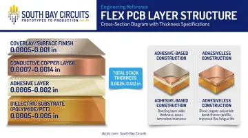
Flex laminates come in two flavors: adhesive-based and adhesiveless. Adhesive-based construction uses a bonding layer between copper and substrate, which works fine for many static applications. Adhesiveless laminate, however, bonds copper directly to the polyimide.
Why does this matter? Adhesive layers have a high z-axis coefficient of thermal expansion, which stresses plated vias and can cause failures over time. Adhesiveless flex avoids this problem, runs thinner, and holds up better in high-temperature or high-flex-cycle environments.
Types of Flex PCBs and How They Compare to Rigid Boards
Not every flex circuit needs the same complexity. Layer count and construction type should match the application's mechanical demands.
Single, Double, and Multilayer Flex Circuits
- Single-sided: One conductive layer with insulation on both sides. Simplest and most affordable option, ideal for basic interconnects.
- Double-sided: Two conductive layers separated by insulation, connected through plated through-holes.
- Multilayer: Three or more flexible conductive layers separated by flexible dielectrics, used when routing density exceeds what two layers can handle.
How many layers can a flex PCB actually have? It depends on the fabricator. Some manufacturers cap practical builds at 1-4 flex layers, since adding more makes the composite stiff and defeats the purpose of going flexible. Others support specialized designs exceeding 20 layers for dense applications.
Rigid-Flex: The Hybrid Approach
Rigid-flex PCBs combine rigid FR-4 sections with flexible polyimide interconnects in a single board. This construction lets designers eliminate cable assemblies and connectors entirely, routing signals directly between rigid zones through a flexible bridge.
Flex vs. rigid vs. rigid-flex, at a glance:
| Type | Substrate | Flexibility | Best Fit |
|---|---|---|---|
| Rigid | FR-4 | None | Component-dense boards, thermal management |
| Flex | Polyimide/PET | High | Space-constrained, folded, or dynamic interconnects |
| Rigid-Flex | Hybrid | Selective | Compact aerospace, medical, defense systems |
Flex fits applications that need to bend once during installation or flex repeatedly in service. Rigid-flex makes more sense when you need to eliminate connectors entirely while still supporting heavy components on rigid zones. Static bending calls for a simpler flex design, while dynamic, repeated motion demands one engineered specifically for fatigue resistance.
Rigid-flex frequently delivers the best balance of durability and space savings, but it also introduces the most design complexity. SBC's single-source model, covering design through assembly under one roof, helps customers work through this decision without coordinating between separate design, fabrication, and assembly vendors.
Critical Flex PCB Design Guidelines
Getting the layout right is where most flex projects succeed or fail. These rules address the most common causes of cracked traces and premature field failures.
Calculating Bend Radius and Defining Bend Areas
Bend radius requirements scale with layer count and total board thickness. As a starting rule, minimum inside bend radius runs about 6x total flex thickness for 1-2 layers and 12x for three or more layers, per All Flex's minimum bend radius guidance.
Other fabricators recommend more conservative multipliers, so always confirm the rule with your specific manufacturer before finalizing a layout.
Two distinct use cases drive different design approaches:
- Static (flex-to-install): Bent once or a few times during assembly, then fixed in place
- Dynamic: Repeatedly flexed in service, sometimes millions of cycles over the product's life
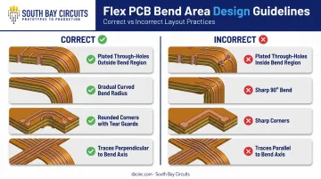
Essential bend-area rules to follow:
- Keep plated through-holes and components out of the bend region entirely
- Avoid sharp 90° bends; use gradual curves instead
- Add rounded corners with tear guards to stop cracks before they start
- Route traces perpendicular to the bend axis wherever possible
Stack-Up and Layer Placement Best Practices
In rigid-flex designs, position flex layers near the center of the stack-up. Sandwiching them between rigid sections protects the flexible material from stress and plating damage during manufacturing.
A few additional practices matter here:
- Stagger traces across layers rather than aligning them directly; aligned conductors stiffen the fold area, while staggered ones preserve flexibility
- Use an even number of layers to maintain a balanced, symmetric stack-up and reduce warpage
- Request a stack-up review from your fabricator early, before the layout is locked in
Vias, Stiffeners, and Component Placement
Vias in dynamic bend areas are a leading cause of trace fracture. Keep them out of the flex zone completely, and maintain a minimum clearance of roughly 0.050 in (1.27 mm) from the rigid-flex transition point.
Stiffeners add mechanical backing under connectors and components that would otherwise stress the thin flex material. As a general guideline, coverlay should overlap the stiffener edge by at least 0.030 in (0.76 mm) to reduce stress concentration at that boundary.
Material Selection for Reliable Flex Circuits
Material choice determines whether a flex circuit survives its intended service life or fails prematurely.
Polyimide is the preferred substrate for most flex applications because of its thermal stability and chemical resistance. Service temperature ranges from -125°C to +200°C, compared to -60°C to +105°C for polyester. Common copper weight options run from 0.5 to 7 oz/ft², with lighter weights preferred for tighter bend radii.
Lamination construction matters just as much as substrate choice: adhesiveless laminates outperform adhesive-based options in a few key areas:
- Moisture resistance: Adhesiveless polyimide shows roughly 0.8% water absorption over 24 hours, versus 2.9% for conventional adhesive-based polyimide
- Dimensional stability: Fewer material layers mean less shift under thermal cycling
- Chemical resistance: Adhesiveless polyimide rates well against strong alkalis, where standard polyimide and polyester underperform
These same material properties carry into coverlay selection, which should follow copper thickness and the operating environment. Thicker copper generally needs thicker adhesive to maintain bond strength, while high-temperature or chemically aggressive environments favor adhesiveless polyimide coverlay over standard alternatives.
Applications Driving Flex PCB Adoption
Flex circuits solve real mechanical problems across several regulated industries.
Medical devices and wearables rely on flex PCBs for compact, comfortable form factors. Smartwatches, fitness trackers, and health monitors all use conformable circuits that reduce weight and bulk while fitting curved enclosures. SBC manufactures these boards under ISO 13485 compliance for medical device work.
Beyond compact consumer designs, aerospace, defense, and automotive systems value flex circuits for weight reduction and vibration resistance. Their ability to flex and absorb mechanical energy makes them well-suited to environments with constant shock and temperature cycling. SBC supports these regulated sectors through:
- ITAR registration and CMMC Level 1 compliance for defense programs
- ISO TS 16949 compliance for automotive manufacturing
- AS9100 compliance for aerospace production
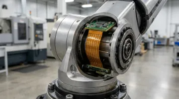
Outside these heavily regulated sectors, industrial equipment and robotics push flex PCBs the hardest. Robot-arm joints, end effectors, and continuous-motion actuators demand circuits engineered for dynamic flexing, often targeting hundreds of thousands to millions of bend cycles without failure.
Flex PCB Cost Factors and Choosing the Right Manufacturing Partner
Flex and rigid-flex boards cost more than equivalent rigid designs. The main drivers include:
- Material choice: Adhesiveless flex laminates run roughly 3-5x the cost of equivalent rigid laminate materials, according to All Flex's rigid-flex cost comparison analysis
- Layer count: More flex layers mean more processing steps and higher scrap risk
- Stiffener requirements: Added material and bonding steps increase both cost and lead time
- Button plating: Selective plating processes add labor compared to standard through-hole plating
- Tighter tolerances: Flex-specific dimensional control requires more precise tooling and inspection
Rigid-flex boards can run considerably higher still. One manufacturer's pricing breakdown shows why:
| Cost Driver | Rigid-Flex vs. Standard Rigid |
|---|---|
| Overall board pricing | About 7x an equivalent hard-board design |
| No-flow prepreg material | $1.50-$3.00/ft² versus roughly $0.25/ft² for standard rigid prepreg |
Here's the part that actually saves money: thorough fab drawings and a DFM review before fabrication starts. Catching a bend-area conflict or an undersized annular ring on paper costs nothing. Catching it after boards are built means a full respin, and that eats weeks off your schedule.
This is where SBC's model earns its keep. With over 40 years in PCB manufacturing, ISO 9001:2015 certification, AS9100 aerospace compliance, and ISO 13485 compliance for medical work, SBC manages design and assembly under one roof.
That single-source structure removes the back-and-forth between separate design, fabrication, and assembly vendors, cutting the finger-pointing that slows projects down when something doesn't fit right.
Frequently Asked Questions
What is a flex PCB?
A flex PCB is a bendable circuit built on a polyimide or PET substrate instead of rigid FR-4. It saves space, reduces weight, and eliminates the need for bulky connectors and wire harnesses.
What is the difference between a flex PCB and a rigid PCB?
Rigid PCBs use FR-4 fiberglass and can't bend, while flex PCBs use flexible polyimide or PET and can fold or flex during installation or service. Rigid boards suit component-dense designs; flex boards fit tight, curved, or moving enclosures.
How many layers can a flex PCB have?
Flex PCBs range from single-sided (one layer) to multilayer configurations with three or more conductive layers. Most practical designs use 1-4 flex layers, though some fabricators support specialized builds exceeding 20 layers.
How much does a flex PCB cost?
Flex PCB materials typically cost 3-5x more than equivalent rigid materials, while rigid-flex boards can run up to 7x a comparable rigid design. Key cost drivers include layer count, stiffeners, and tolerance requirements.
What is the minimum bend radius for a flex PCB?
Bend radius depends on layer count and total thickness. A common starting guideline is 6x total thickness for 1-2 layers and 12x for three or more layers, though specific multipliers vary by fabricator.
Can a flex PCB be repaired if damaged?
Flex PCB repair is more challenging than rigid board repair due to thin substrates and embedded traces. IPC-7711C/7721C includes procedures for trained technicians, but prevention through proper design remains the better strategy.