The global medical-electronics market, which includes diagnostic, monitoring, and implantable equipment, is projected to grow from $11.1 billion in 2024 to $15.7 billion by 2029, according to MarketsAndMarkets. That growth is pushing more devices, and more PCBs, into direct contact with patient care.
Medical PCB design isn't consumer electronics with a stricter label slapped on. It demands different materials, tighter tolerances, and a compliance framework most engineers outside the industry never encounter. This guide covers the regulatory standards, material choices, and miniaturization strategies that matter, along with how to pick a manufacturing partner, drawing on South Bay Circuits' four decades of contract manufacturing experience.
Key Takeaways
- Medical PCBs need IPC Class 3 and ISO 13485 compliance—well above IPC Class 2 consumer standards
- Material choice—FR-4, polyimide, ceramic, or flex/rigid-flex—drives signal integrity, biocompatibility, and device lifespan
- HDI, via-in-pad, and SMT leave less layout margin as devices shrink—DFM must start earlier
- Bringing a manufacturing partner in early cuts redesign cycles and speeds up regulatory approval
Regulatory Standards & Compliance Requirements
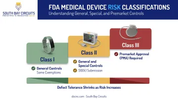
Medical device PCBs face oversight most electronics never see because failure isn't just an inconvenience. The FDA sorts devices into three risk-based tiers, and that classification drives everything downstream:
- Class I devices carry the lowest risk and fall under General Controls, with some exemptions
- Class II devices need General and Special Controls, usually cleared through a 510(k) submission
- Class III devices carry the greatest risk and typically require Premarket Approval (PMA)
The higher the classification, the less room a PCB has for defects. An implantable pacemaker board and a consumer fitness tracker board might look similar under a microscope, but their reliability requirements are worlds apart.
Key Standards Every Medical PCB Designer Must Know
Four standards form the backbone of medical PCB compliance:
- ISO 13485:2016 — Sets quality management system (QMS) requirements for any organization designing, producing, or servicing medical devices
- FDA 21 CFR Part 820 / QMSR — Governs finished-device manufacturing controls; the updated QMSR (effective February 2, 2026) incorporates ISO 13485 by reference
- IEC 60601-1 — Covers basic electrical safety and essential performance for medical electrical equipment
- ISO 14971:2019 — Requires lifecycle risk management, from hazard identification through post-market monitoring
Layered on top of these is IPC Class 3, the highest reliability tier in IPC's board standards. It demands tighter conductor spacing, stricter plating and annular ring checks, and zero tolerance for defects that might pass on consumer-grade Class 2 boards.
For implantable or life-sustaining devices, Class 3 isn't optional. It's the default expectation.
Documentation, Traceability & Record-Keeping
Passing an FDA or ISO audit comes down to paperwork as much as engineering. Reviewers want to see:
- Lot traceability tying every component back to its source
- Device History Records (DHR) documenting how each unit was built and tested
- Test and inspection records proving the board met spec before shipment
The stakes are real. One FDA Class 2 recall involved a ventilator power circuit board assembly where a component failure could disable both ventilation and the caregiver alarm (FDA recall database). That's the kind of failure traceability records exist to catch before a device ever reaches a patient.
Before signing a contract, vet manufacturers for a documented quality system that can produce IPC Class 3 electronics, not just claim it. SBC runs production through an ERP system that tracks component and process traceability across every work order—infrastructure auditors expect to review.
Material Selection for Medical-Grade PCBs
Material choice isn't a cosmetic decision. It determines signal loss, biocompatibility, and how long a device survives inside or against the human body. The right substrate depends heavily on whether the board is going into a wearable, an implant, or a bench-top diagnostic unit.
Common Substrate Options and Their Best Use Cases
| Material | Typical Dielectric Constant | Best Fit |
|---|---|---|
| High-Tg FR-4 (e.g., Isola FR408HR) | ~3.6–3.7 | Non-implantable diagnostic and monitoring equipment |
| Polyimide (e.g., DuPont Pyralux AP) | ~3.2–3.4 | Flexible circuits, prosthetics, wearable sensors |
| PTFE (Rogers laminates) | Low, RF-optimized | High-frequency imaging and RF applications |
| 96% Alumina ceramic | ~9.8 | High-thermal-conductivity power electronics |
FR-4 remains the workhorse for cost-sensitive, non-implantable designs, but it isn't automatically biocompatible just because it's common.
Polyimide earns its place in flexible and implant-adjacent applications thanks to strong tensile strength and thermal stability. Manufacturer datasheets often caution against permanent implantation without additional qualification.
PTFE laminates fit high-frequency imaging and RF paths where low dielectric loss matters more than unit cost. Ceramic substrates carry a higher dielectric constant than most engineers expect, but their thermal conductivity (often 20+ W/m·K) makes them valuable where heat dissipation matters more than signal speed.
Flexible, Rigid-Flex & Protective Coating Considerations
Flex and rigid-flex boards reduce connector count and weight while conforming to body shapes. That flexibility is why they've become popular in wearables and compact implants like cochlear devices and hearing aids. SBC supports flex and rigid-flex construction using polyimide substrates alongside its broader laminate portfolio.
Conformal coatings add another layer of protection:
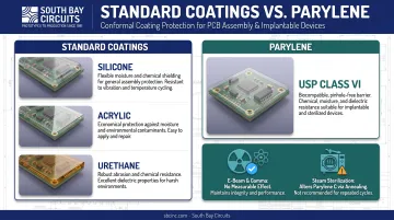
- Silicone, acrylic, and urethane: Applied in SBC's standard assembly processes to shield boards from moisture and chemical contaminants
- Parylene: Used for USP Class VI biocompatibility and chemical resistance in implantable and sterilized devices
Sterilization method matters as much as the coating choice. Research on Parylene coatings found that e-beam and gamma sterilization had no measurable effect on tensile properties, while steam sterilization altered Parylene C through an annealing effect. There's no universal "safe for X cycles" number. Each coating and sterilization pairing needs its own validation.
Design Considerations: Miniaturization, Signal Integrity & Reliability
Medical devices keep shrinking, and every millimeter saved tightens the design margin for error. A misplaced via that would be a minor inconvenience on a desktop appliance board can be a functional failure on an implantable sensor.
HDI, Via-in-Pad & SMT for Compact Boards
High-Density Interconnect (HDI) design, using blind and buried vias plus via-in-pad techniques for BGAs, has become standard for compact medical boards. Meeting IPC Class 3 tolerances at this scale generally requires laser direct imaging and modified semi-additive processing (mSAP), since traditional etching can't hold the tighter registration these designs demand.
SMT has largely replaced through-hole mounting in medical designs for good reason:
- Smaller component footprints free up board real estate
- No drilling means fewer mechanical stress points
- Assembly runs faster with less manual handling
Just how small can components get? Murata's 008004 MLCC measures 0.25mm × 0.125mm × 0.125mm, smaller than a grain of sand. SBC's own trace/space capability runs down to .002"/.002" on demanding designs, with .004"/.004" typical—precision that matches this component scale.
EMI/EMC, Signal Integrity & Thermal Management
Medical devices don't operate in isolation. They sit near other electronics in hospitals, ambulances, and homes, so grounding and shielding strategies matter for meeting IEC 60601-1-2's EMC requirements.
Signal integrity needs the same early focus. Controlled impedance routing, continuous return paths, and tight differential-pair geometry keep high-speed sensor and comms lines clean as traces shrink and stackups densify.
Thermal simulation belongs in layout, not after a board is built. Finding hot spots in the 3D model before fabrication is far cheaper than catching them with post-production infrared analysis.
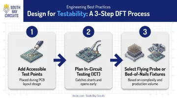
Reliability also hinges on catching defects before devices reach patients. Design-for-test (DFT) practices should be built in from the start:
- Add accessible test points during layout, not as an afterthought
- Plan for in-circuit testing (ICT) using electrical probes to catch shorts and opens early
- Consider flying probe or bed-of-nails fixtures depending on board complexity and volume
SBC applies DFT evaluation as a standard part of its layout process across mixed-technology, BGA, and high-speed board designs, which helps catch testability gaps before they become field troubleshooting headaches.
Best Practices for Working with a Medical PCB Manufacturing Partner
Getting a manufacturer involved before layout is finalized isn't a nice-to-have. It's how costly redesigns get avoided. DFM and DFT expectations need alignment from day one, not after Gerber files are already locked.
A single-source partner that manages design, fabrication, assembly, and box build under one roof eliminates the handoff errors that creep in when three different vendors touch the same project.
South Bay Circuits has operated for over 40 years from its 60,000-square-foot Chandler, Arizona facility. It is ISO 9001:2015 certified and supports an ISO 13485-aligned quality system for medical-device manufacturing. Rapid-turn programs include 24-hour fabrication and same-day assembly, with timelines set by layer count, materials, and design complexity.
Before signing a contract, confirm these capabilities:
- Component obsolescence management: How the manufacturer handles end-of-life parts and long-term sourcing, since a forced substitution mid-lifecycle can trigger regulatory resubmission delays
- Quality documentation: Lot tracking and test records should meet ISO 13485 and FDA audit expectations, not just general ISO 9001 requirements
- Traceability infrastructure: An ERP system that tracks component and process data across BOM management, work orders, and inventory (SBC's system does this end to end)
Vendor Managed Inventory, Just-In-Time, and Kanban programs can also help medical OEMs avoid the sourcing gaps that force last-minute design changes late in a product's regulatory life.
Frequently Asked Questions
How much do medical device consultants charge?
Fees vary widely by scope. As a benchmark, one regulatory consulting firm's 2025 rate card lists senior consultants at $375–$450/hour, specialists at $275–$325/hour, and associates at $150–$200/hour.
What is IPC Class 3 and why is it required for medical PCBs?
IPC Class 3 is the highest reliability tier in IPC's board standards, demanding tighter tolerances and near-zero defect criteria. It's the expected standard for implantable and life-sustaining devices where failure isn't an acceptable outcome.
Can FR-4 be used in medical device PCBs?
Yes, for many non-implantable diagnostic and monitoring devices. High-frequency or implantable applications generally need specialized laminates like polyimide or PTFE instead.
What's the difference between flex and rigid-flex PCBs for medical devices?
Flex PCBs suit compact, bendable wearables where weight and conformability matter most. Rigid-flex combines rigid mounting sections with flexible interconnects, better suited for complex, more durable assemblies.
What certifications should a medical PCB manufacturer have?
Look for ISO 13485 compliance, ISO 9001:2015 certification, and demonstrated IPC Class 3 production capability. These three together indicate both quality systems and technical capacity.
How long does it take to prototype a medical device PCB?
Timelines depend on layer count and design complexity. Partners with quick-turn prototype and assembly capability—same-day to a few days in some cases—can compress schedules significantly versus standard multi-week cycles.