Introduction
Every printed circuit board comes down to one core decision: how do the components attach to it? Surface-mount devices (SMD) solder directly onto pads. Through-hole components thread leads into drilled holes and anchor on the opposite side.
That single choice ripples through everything else: board size, manufacturing cost, how the product handles vibration, and how quickly a design moves from prototype to full production.
Engineers and buyers who understand the tradeoffs make better calls on budget, reliability, and timelines. Get it wrong, and you are either overpaying for miniaturization you don't need or building a board that can't survive its own operating environment.
This article breaks down what SMD and through-hole actually are, compares them side by side, and shows how most functional boards today blend both technologies rather than picking one exclusively.
Key Takeaways
- SMD parts solder to surface pads; through-hole leads pass through plated holes for mechanical anchor strength
- Dense, high-volume automated builds favor SMD; high-stress, high-power, or serviceable designs favor through-hole
- Most production boards mix both technologies, placing each component where it fits best
- The right technology mix with a capable manufacturing partner beats favoring one method alone
SMD vs Through-Hole: Quick Comparison
Here's how SMD and through-hole compare on the factors that drive most production decisions.
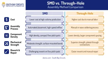
| Factor | SMD | Through-Hole |
|---|---|---|
| Cost | Lower per-unit cost at volume; stencil/programming costs rise with design changes | Higher labor cost per joint at scale; lower tooling cost for prototypes and short runs |
| Assembly Process | Solder paste stencil printing, pick-and-place, reflow oven soldering | Manual insertion or wave soldering through drilled holes |
| Component Density | Compact packages allow double-sided population and high density | Larger footprint, generally lower placement density |
| Mechanical Strength | Adequate for light components; vulnerable to vibration or connector-mating stress | Leads anchor through the board's full thickness, ideal for connectors and heavy parts |
| Rework & Repair | Complex, especially for fine-pitch or BGA packages | Straightforward manual desoldering and replacement |
Mechanical strength is the clearest split. Electropages notes that through-hole generally holds up better against vibration, shock, and thermal cycling, which is why connectors and power components still rely on it.
On cost, no single per-board dollar figure fits every project. The pattern is consistent: automation favors SMD at scale, while THT avoids upfront tooling costs on short runs.
Turnaround follows similar logic. Whether you run SMT-only or mixed-technology boards, schedule depends more on design complexity and quote-specific factors than on mounting method alone.
What is an SMD Component?
An SMD (surface-mount device) is a component soldered directly onto pads on the board's surface, using surface-mount technology, or SMT, rather than passing through drilled holes. No holes, no leads threading through layers: just a component sitting on a pad, held by solder paste and heat.
Operationally, SMT enables faster automated placement, smaller footprints, and consistent quality at scale. That cuts per-unit assembly time compared to manual insertion methods.
Common SMD Package Types
SMD components come in a range of sizes and configurations:
- Passive packages like 0402 and 0603 chip resistors and capacitors
- IC packages such as SOIC, QFN, and BGA
- Fine-pitch and micro-BGA devices, increasingly common in dense digital boards
- Larger SMD parts, including transformers and other bulky components in surface-mount versions
Use Cases of SMD
SMD dominates automated, high-volume lines building compact boards. That includes smartphones and wearables, and it also covers medical devices, industrial controls, aerospace electronics, and RF/high-frequency designs, where shorter leads cut signal noise and parasitic inductance.
SMT held over 72.7% of the global PCBA market in 2025, according to Grand View Research. That share shows where most modern electronics manufacturing has landed.
South Bay Circuits runs this end of the spectrum on fully automated Fuji SMT lines, with standard placement down to 0201 packages and fine-pitch capability to 0.3mm and smaller under engineering review. Micro-BGA and HDI assemblies get verified through X-ray inspection before they ship.
What is a Through-Hole Component?
Through-hole mounting inserts a leaded component into drilled, plated holes and solders it on the opposite side of the board. It's the older method, but it hasn't gone anywhere, because some applications need reliability more than they need miniaturization.
The core advantages are mechanical, not electrical. Through-hole joints form stronger physical bonds, allow simpler field rework, and handle high-voltage or high-current loads better than most surface-mount alternatives.
Axial vs. Radial Leads
Through-hole components come in two lead configurations:
- Axial leads extend from opposite ends of the component body — common on resistors, fuses, and LEDs
- Radial leads extend from the same side — typical for ceramic capacitors
Use Cases of Through-Hole
Connectors, transformers, and power modules that face repeated mating cycles or mechanical stress rely heavily on through-hole mounting. The lead-through-hole joint simply handles physical load better than a surface pad.
That is why through-hole shows up so often in aerospace, defense, automotive, and medical device manufacturing, where ruggedness and certification requirements carry real weight. High-reliability programs in these fields, including those built around standards like IPC Class 3, frequently specify through-hole for the most mechanically critical joints, even when surface-mount covers everything else.
Industrial, aerospace, medical, and control-electronics assemblies commonly mix both technologies, reserving through-hole for connectors, power parts, fuses, and other ruggedized components.
South Bay Circuits handles those mixed builds in-house with wave and hand soldering, running axial and radial components through a dual-pot solder wave system and finishing with a water-soluble flux and deionized-water rinse for contamination-free joints.
SMD vs Through-Hole: Which One Is Better for Your Application?
There's no single right answer here. The correct call depends on weighing a handful of factors against your specific design goals:
- Production volume — high-volume runs favor SMD's automation advantages
- Mechanical/vibration exposure — harsh environments favor through-hole's anchoring strength
- Available board space — tight layouts push toward SMD's smaller footprints
- Budget — prototype and low-volume runs often favor through-hole's lower tooling cost
- Rework and repair needs — field-serviceable products favor through-hole's simpler desoldering
As a general rule: choose SMD for compact, high-volume, automated builds. Choose through-hole for ruggedized, high-power, or field-serviceable designs where a component cannot fail under stress.
Real-World Scenario: When Mixed Assembly Wins
Products in aerospace, medical, and automotive electronics rarely fit neatly into one category. A single board might need dense SMD circuitry for signal processing right next to a rugged through-hole connector or power module that has to survive years of vibration and repeated mating cycles.
Forcing one technology onto the whole board doesn't work here. Mixed-technology assembly places each component based on its own electrical and mechanical needs: SMD for the dense digital section, through-hole for the connectors and power stage.
The bigger risk in these projects usually isn't the technology mix itself. It's coordination. When SMT assembly happens at one shop and through-hole or wave soldering happens at another, every handoff adds shipping time, queue delays, and a chance for something to get lost between vendors.
That handoff also invites finger-pointing when a defect shows up and neither shop wants to own it.
South Bay Circuits addresses this by running SMT and through-hole/wave soldering under one roof at its Chandler, Arizona facility. Design, fabrication, and assembly stay in the same building, which removes the handoff points where delays and the "blame game" typically creep in.
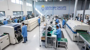
The right technology mix, executed by a manufacturing partner who can run both processes without outsourcing either one, drives reliability and speed more than any single mounting method on its own.
Have a mixed-technology design that needs a second set of eyes? South Bay Circuits' engineering team can review your layout for optimal SMD and through-hole placement before it goes into production.
Conclusion
There's no universal winner between SMD and through-hole. The right decision comes from matching each component's space, stress, volume, and repairability requirements to the mounting method that fits it best — and on most real boards, that means using both.
Getting this mix right pays off in cost efficiency, durability, and faster production cycles. Partner with a single-source manufacturer like South Bay Circuits that handles SMT, through-hole, and mixed-technology assembly under one roof—so you avoid the delays and handoff gaps that come from splitting the work across separate vendors.
Frequently Asked Questions
What is the difference between SMD and THT?
SMD mounts components directly on the board's surface with no holes required, enabling smaller and denser boards. THT uses leads inserted into drilled holes, creating a stronger mechanical bond at the cost of board space.
What is the difference between an SMD resistor and a through-hole resistor?
SMD resistors are small rectangular chips, like 0402 or 0603, soldered flat onto pads for automated placement. Through-hole resistors have axial leads inserted into holes and soldered manually or via wave soldering.
Can SMD and through-hole components be used on the same PCB?
Yes — mixed-technology boards are common. The typical order runs SMT reflow first, followed by through-hole insertion and soldering, though pin-in-paste processes can combine both steps in some cases.
Which is cheaper, SMD or through-hole?
SMD is generally more cost-effective at volume thanks to automation. Through-hole can be cheaper for small prototype runs since it avoids stencil and setup costs tied to SMT equipment.
Is through-hole technology becoming obsolete?
No. Through-hole remains essential for high-reliability, high-power, and field-serviceable applications, even though SMT dominates overall production volume across the industry.
Which technology is more reliable in high-vibration or harsh environments?
Through-hole generally offers stronger mechanical retention under vibration and shock, making it the preferred choice for aerospace, automotive, and military-grade applications.