Introduction
A circuit card assembly (CCA) is the finished, functional building block behind systems your products depend on, from a pacemaker to a jet's flight control system. Yet many engineers and buyers use "CCA," "PCB assembly," and "circuit card" interchangeably, and that mix-up gets expensive fast.
Specify the wrong term on a quote request, and you might get a bare board when you needed a fully populated, tested assembly. That mismatch delays projects and inflates costs.
This guide breaks down what a CCA actually is, its core components, the manufacturing process step by step, the assembly technologies involved, and how to choose a partner for high-reliability work.
Key Takeaways
- A CCA is a populated PCB with soldered components and connectors, fully tested and ready to function
- SMT and THT are the two primary assembly technologies, often combined in mixed-technology builds
- AOI, ICT, X-ray, and functional test should all clear before any production release
- "CCA," "PCBA," and "PCA" name the same finished board; CCA is preferred in defense, aerospace, and medical
What Is a Circuit Card Assembly?
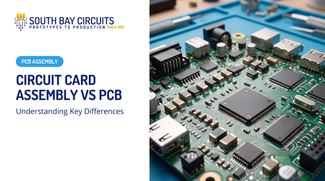
A circuit card assembly is a printed circuit board that has been populated with electronic components—resistors, capacitors, ICs, connectors—and soldered into a complete, functional module. Think of it as the difference between a blank canvas and a finished painting.
A bare PCB, by contrast, has no components at all. It's just the substrate, copper traces, solder mask, and silkscreen. The bare board is only the interconnect structure; the CCA is the working electronic module.
This distinction matters more than most buyers realize. Specifying "PCB" versus "CCA" or "PCBA" on a quote request changes the scope, cost, and lead time dramatically:
- A bare PCB quote covers fabrication only
- A CCA quote covers components, soldering, inspection, and testing
- Mixing up the two terms often leads to incomplete quotes or missed project deadlines
What Is a Circuit Card?
"Circuit card" shows up constantly in defense and aerospace, and it can mean two different things. Sometimes it means the bare board; more often in CCA work, it means the assembled board.
NASA's spacecraft-electronics guidance, for example, tells technicians not to apply conformal coating to a "circuit card assembly" until it has passed full functional testing. That usage treats the CCA as the populated, tested board, not the raw substrate.
IPC documentation tends to favor "printed board assembly," so the label you see usually reflects industry convention rather than one universal rule.
Circuit Card Assembly vs. PCB Assembly: What's the Difference?
Here's the short answer: there isn't much of one. CCA and PCBA (Printed Circuit Board Assembly) both describe a bare board populated with soldered components. The terminology split comes down to industry habit, not a technical distinction.
- CCA: Preferred in defense, aerospace, and industrial work; often signals IPC-A-610 Class 2 or Class 3 workmanship plus full traceability
- PCBA: Broader commercial term used across consumer and industrial electronics
Neither label is more correct on its own. Use the term your industry and customer specs expect so quotes, quality clauses, and deliverables stay aligned.
Key Components of a Circuit Card Assembly
Every CCA is built from a handful of core elements. The quality of each one determines how the finished assembly performs in the field.
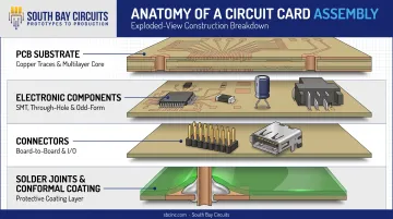
PCB Substrate
The substrate is the foundation: the layer that holds copper traces, solder mask, and silkscreen in place.
Common materials include standard FR-4, high-temperature FR-4 (rated at 170°Tg), polyimide, and specialty RF laminates such as Rogers 3000/4000 or Nelco N4000 series. Flex and flex-rigid constructions are also common when space or bend requirements demand them.
Electronic Components
Passive and active parts give the assembly its function. Packaging dictates the mounting method:
- Surface-mount parts sit directly on the board
- Through-hole parts need drilled holes and leads
- Odd-form parts (often connectors) mix both approaches
Tolerance matters. A thin-film chip resistor might hold 0.01% resistance tolerance, while a commercial-grade capacitor might range from ±0.5 pF to ±10% depending on the series. Choosing the wrong tolerance for your application is a common, costly mistake.
Connectors
Board-to-board, I/O, and wire-to-board connectors let the CCA talk to power sources, sensors, and other system components. They are often the odd-form, through-hole parts on an otherwise SMT-heavy board.
Solder Joints and Conformal Coating
Beyond the parts themselves, joint quality and protection decide long-term reliability.
Solder joint quality is the single biggest driver of mechanical and electrical reliability on any CCA. IPC-A-610 sets the acceptance criteria manufacturers use, with three progressive classes (1, 2, and 3) that raise performance and inspection requirements.
Conformal coatings (typically silicone, acrylic, or urethane) add a protective layer that shields circuitry from moisture and chemical contaminants. Matching the coating type to the product’s operating environment is part of a complete assembly process at South Bay Circuits.
The Circuit Card Assembly Process: Step by Step
Building a CCA follows a consistent sequence, whether you're running a single prototype or a high-volume production order.
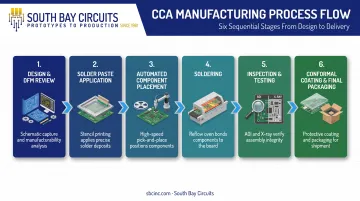
Design & DFM Review. Engineers finalize schematics and layouts, then run a Design for Manufacturability check to catch footprint mismatches, spacing problems, and thermal concerns before they become expensive production defects.
Solder Paste Application. Operators stencil-print solder paste onto PCB pads for surface-mount components. Too much paste causes bridging; too little creates weak joints.
Automated Component Placement. Pick-and-place machines position SMT components at high speed with micron-level accuracy. Panasonic's NPM-GH platform, for example, places up to 55,500 components per hour with accuracy as tight as ±10 µm. South Bay Circuits runs Fuji CP-642 and CP-65 chipshooters with a Fuji IP-3 flexible placer to handle a wide range of component sizes and volumes.
Soldering. Reflow ovens bond SMT components; wave or selective soldering secures through-hole parts. Mixed-technology boards need both processes run in sequence. SBC handles this in-house using BTU VIP 70 and Conceptronic HVA-70 reflow ovens paired with a Manncorp dual-pot wave soldering system.
Inspection & Testing. This stage catches defects before boards ship:
- AOI visually checks solder quality and component placement
- X-ray reveals hidden joints under BGAs and similar packages
- ICT probes for shorts, opens, and incorrect component values
- FCT verifies the board works under real operating conditions
South Bay Circuits runs all four in-house: Marantz NSPEC FV18 (AOI), Teradyne Z1860VP with 2,048 test points (ICT), Glenbrook Jewel Box 70T (X-ray), and NI-PXI-1042 systems (functional test).
Conformal Coating & Final Packaging. Boards receive protective coatings for harsh-environment durability, then serialized, lot-coded packaging for full traceability before shipment.
SMT, Through-Hole, and Mixed Technology Assembly
Most CCAs today rely on some combination of two mounting technologies, and understanding both helps you spec the right approach for your product.
The three approaches differ in how parts attach and where each pays off:
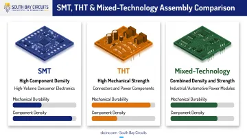
- SMT — components mount on the board surface for density and high-volume builds
- THT — leads pass through drilled holes for superior mechanical strength
- Mixed — both methods on one board when density and ruggedness are required
Surface-Mount Technology (SMT) mounts components directly onto the board surface. That higher density supports the miniaturized, high-volume production industrial and commercial electronics rely on today. South Bay Circuits places SMT components down to 0.4mm pitch, with finer geometries available following engineering review, and supports micro-BGA and HDI components as standard capability.
Through-Hole Technology (THT) runs component leads through drilled holes in the board, then solders them on the opposite side. This gives superior mechanical strength, which is why connectors, transformers, relays, and other high-stress components still rely on THT even on otherwise SMT-dominant boards.
Mixed-Technology Assembly combines both approaches on a single board. It's especially common in industrial and automotive power modules, where you need SMT density for logic and control alongside THT ruggedness for connectors and power components.
One EMS provider reported that nearly 75% of the boards it manufactured combined SMT and THT. Pure single-technology boards are increasingly the exception, not the rule.
South Bay Circuits supports all three approaches from the same Chandler, Arizona facility, which matters when your BOM calls for both fine-pitch SMT parts and rugged through-hole connectors on the same board.
Choosing the Right CCA Manufacturing Partner
Not every contract manufacturer is built for high-reliability work. Here's what actually separates a reliable partner from a risky one.
Certifications should match your industry. ISO 9001 covers general quality management, but it's not sector-specific. For aerospace and defense work, look for AS9100 compliance, which adds sector-specific controls on top of ISO 9001. Medical device programs need ISO 13485. Automotive work needs IATF 16949.
South Bay Circuits holds ISO 9001:2015 through UL-DQS (Certificate #10000903 QM15) and maintains AS9100, ISO 13485, and ISO/TS 16949 compliance. SBC is also ITAR registered and CMMC Level 1 compliant, which matters for defense CCA work involving items on the U.S. Munitions List.
Prioritize single-source manufacturers. Splitting design, fabrication, and assembly across three vendors multiplies queue time, shipping delays, and finger-pointing when something goes wrong. A single-source model removes those handoffs.
That model is how South Bay Circuits has operated since 1981: 24-hour PCB fabrication and same-day assembly for prototypes, with a documented 3-day-or-less turn for standard PCB assembly.
Confirm in-house testing, not outsourced. Outsourced inspection adds shipping time and reduces accountability when defects surface. Ask specifically:
- Does the manufacturer run AOI, ICT, X-ray, and functional test on-site?
- Can they show you the actual equipment—not just a checklist?
- Do they offer full traceability through serialized lot coding?
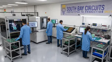
South Bay Circuits runs its full inspection suite in-house, from optical inspection through functional test, so defects get caught without waiting on a third party.
Frequently Asked Questions
What is a circuit card assembly?
A circuit card assembly is a printed circuit board populated with soldered electronic components and connectors. It forms a complete, functional electronic module ready for use in a device or system.
What is a circuit card?
"Circuit card" is often used interchangeably with PCB, but in CCA discussions it typically refers to the assembled board rather than the bare substrate, following common defense and aerospace usage.
What is the difference between circuit card assembly and PCB assembly?
Both terms describe the same finished product: a populated, soldered board. CCA is more common in high-reliability sectors and often implies stricter testing and traceability standards.
What is the difference between a CCA and a bare PCB?
A bare PCB has no components; it's just the substrate, copper traces, and solder mask. A CCA is the fully populated, soldered, and tested version ready to perform its function.
What certifications should a CCA manufacturer have for aerospace or medical applications?
Look for AS9100 for aerospace work and ISO 13485 for medical devices, both built on a baseline ISO 9001:2015 quality management certification.
How long does circuit card assembly typically take?
Turnaround depends on complexity and volume, but standard assembly often runs three days or less. Quick-turn providers can offer 24-hour fabrication and same-day assembly for prototypes.