Introduction
Every solar array, UPS unit, and EV drivetrain hides a board doing the real work: turning stored DC power into usable AC. Most OEM teams never see it until something fails—and that's the problem.
Misjudging how an inverter circuit board is built—or picking the wrong manufacturing partner—often shows up later as premature failure, unplanned downtime, or a redesign that costs more than the original build.
A board that looks fine on a datasheet can still overheat in the field if thermal design was never validated against the real load profile.
This guide covers how inverter PCBs work, what goes into them, where they’re used, how they fail, and what to demand from a manufacturing partner.
Key Takeaways
- Inverter PCBs convert DC to AC using MOSFET or IGBT switching, then shape the output into a clean sine wave with filtering.
- Board complexity, layer count, and thermal design scale directly with power output and application risk.
- Overheating, capacitor aging, and moisture ingress are the leading causes of premature board failure.
- Single-source manufacturers with in-house design, fabrication, and assembly cut cycle time and reduce handoff errors.
What Is an Inverter Circuit Board and How Does It Work?
An inverter circuit board is the PCB responsible for DC-to-AC conversion inside any inverter system, whether it's mounted in a solar array, a UPS cabinet, an EV powertrain, or an industrial drive. It is the electronic core of the inverter.
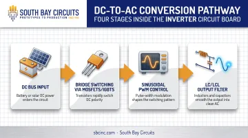
The conversion happens through rapid switching. Power semiconductors—MOSFETs or IGBTs—arranged in a bridge configuration flip the DC current back and forth at high frequency. In a full-bridge design, high-side and low-side transistors alternate to apply positive and negative voltage across the load, and sinusoidal PWM (pulse-width modulation) controls how that switching happens over time.
But switching alone produces a rough, stepped waveform, not usable AC. That's where filtering comes in:
- An LC or LCL output filter smooths the switched signal into a genuine sine wave
- The filter stage matches output to the required voltage and frequency
TI's reference design for a 380V DC bus shows this pattern clearly: MCU-generated sinusoidal PWM drives the bridge, then an L-C-L filter shapes the final AC output.
Control Functions vs. Power Conversion
These are two separate jobs on the same board. The bridge transistors handle raw energy switching. The control circuitry handles a different set of tasks: generating PWM signals, managing gate drive timing, monitoring DC-bus and current levels, and triggering shutdown on overtemperature, overload, or short-circuit conditions.
Texas Instruments documents this division clearly in three-phase IGBT-based inverter designs, where six isolated gate drivers manage the power stage while a separate control loop handles feedback and protection.
How complex that board gets depends on power output. A small portable inverter might use a single MOSFET pair with basic filtering. A multi-kW three-phase industrial board needs six switching devices, isolated gate drivers, and layered protection logic.
In most enclosures, the board does not work alone. It typically pairs with a transformer and an output filter stage to complete the conversion path.
Key Components Inside an Inverter Circuit Board
Every inverter PCB is built from three functional groups. Understanding them helps explain why some boards last a decade and others fail in months.
Power components handle high current and voltage:
- MOSFETs/IGBTs: switch the DC bus on and off to build the AC waveform
- Diodes: manage current flow direction and protect against reverse voltage
- Capacitors: smooth the DC link and absorb ripple current
- Inductors: filter switched output into a usable sine wave
Control components keep the switching accurate:
- Microcontrollers: generate the PWM timing
- Driver ICs: translate low-power signals into the voltage levels needed to switch high-power transistors
- Isolation: separates control and power domains to prevent damaging feedback
Protection components shut the system down before damage spreads:
- Fuses: interrupt short-circuit or overload current with minimal let-through energy
- Sensors: feed current and thermal data back to the control loop
- Fault detection: triggers automatic shutdown on overtemperature or ground fault
Structural Elements That Determine Reliability
The substrate matters more than most buyers realize. Standard FR4 works for many designs, but it has relatively high thermal resistance. Boards running hot loads often need thermal vias under power components to move heat into an internal ground plane.
Some designs use a metal-core substrate instead, which dissipates heat more effectively than a standard FR4 stackup.
Copper trace thickness also affects current-carrying capacity and heat spread. South Bay Circuits works with substrate options for power-electronics builds that include high-temperature FR4 rated at 170Tg, plus Rogers 3000/4000 series and Nelco laminates for demanding thermal or RF requirements.
Layout discipline ties it together. Separating high-power switching zones from sensitive control circuitry, and keeping trace routing tight, minimizes EMI that would otherwise corrupt feedback signals or cause nuisance shutdowns.
Types of Inverter Circuit Boards
Not every inverter needs the same board complexity. Layer count and construction generally track with power level and design density, though the mapping isn't a hard rule.
Single-Sided PCBs
These carry conductive traces on one side only. They're the simplest and cheapest option, suited to low-cost, low-power inverters with basic circuitry, such as small portable DC-to-AC converters where component count stays minimal.
Double-Sided PCBs
Double-sided boards route traces on both surfaces, connected through plated through-holes. This construction supports more components and denser interconnections. It fits mid-range applications like residential inverters and motor control boards that need more circuitry than a single-sided layout can handle.
Multilayer PCBs
Multilayer boards stack additional conductive layers with dedicated power and ground planes. Sierra Circuits notes that these extra layers support denser routing while the planes provide clean return paths, reducing EMI and improving signal integrity. That's exactly what industrial drives, EV traction inverters, and other high-performance systems need, since noisy switching signals can otherwise interfere with control-loop accuracy.
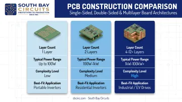
South Bay Circuits fabricates single-sided, double-sided, and multilayer boards, with documented capability extending to 22-plus layer designs for high-density interconnect builds.
Applications of Inverter Circuit Boards Across Industries
Inverter PCBs show up anywhere DC power needs to become usable AC, but the design requirements shift dramatically by industry.
- Renewable energy systems: Solar and hybrid inverters pair an MPPT-controlled DC-DC stage with a downstream DC-AC stage. TI's solar inverter architecture uses six synchronized PWM signals to switch the DC bus into grid-ready three-phase AC.
- Backup power and UPS: Data centers and hospitals depend on UPS inverter boards for seamless AC the instant utility power drops. Fast switchover logic and stable output under sudden load changes are essential.
- Industrial motor drives: Heavy machinery needs balanced three-phase output. Drive boards commonly use six switching devices with field-oriented control and phase-current sensing to hold torque and speed across varying loads.
- High-reliability sectors: Aerospace, defense, medical, and automotive programs require inverter electronics built to strict quality standards.
South Bay Circuits manufactures inverter and power-conversion PCBs under ISO 13485 for medical, AS 9100 for aerospace, and ISO/TS 16949 for automotive programs. In these sectors, traceability and process control matter as much as electrical performance.
Signs Your Inverter Circuit Board Is Failing (and What Affects Its Lifespan)
Catching a failing board early saves both money and downtime. Watch for these warning signs:
- No AC output at all, or output that cuts in and out intermittently
- Unusual buzzing, clicking, or humming noise from the enclosure
- A burning smell, especially near the power stage
- Visibly blackened, bulging, or corroded components
Overheating is the most common root cause. It ties directly back to thermal design: insufficient copper weight, missing thermal vias, or a substrate that can't shed heat fast enough all accelerate component stress over time.
Moisture is another major factor, particularly for outdoor solar installations or industrial sites with humidity swings. NREL's research on film capacitors identifies humidity, temperature, and voltage stress as key drivers of corrosion, ion migration, and eventual capacitor degradation.
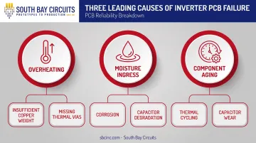
Even without a single dramatic fault, components wear down gradually. Capacitors age, semiconductor junctions accumulate thermal cycling stress, and performance eventually drifts outside spec.
There's no universal lifespan figure. Life expectancy depends heavily on mission profile:
- Thermal cycling frequency
- Load stress
- Installation environment
Before assuming a full board swap is necessary, test with a multimeter or oscilloscope to confirm whether the fault is isolated to one component or affects the whole power stage.
Cost Factors and Choosing the Right Inverter PCB Manufacturing Partner
Inverter PCB pricing depends on several concrete variables, not a flat per-board rate.
Main cost drivers include:
- Board size and layer count (more layers mean more production steps and material)
- Copper thickness (heavier copper for current-carrying traces adds cost)
- Substrate and material class (high-temp FR4 or specialty laminates cost more than standard FR4)
- Required certifications and testing (added test coupons and inspection steps raise price)
Boards destined for aerospace, medical, or automotive programs typically cost more than general industrial equivalents. That premium comes from stricter testing protocols, full material traceability, and documentation requirements tied to the relevant quality system, not from the board materials themselves.
Why Single-Source Manufacturing Matters
Splitting design, fabrication, and assembly across separate vendors adds shipping time and communication lag between every handoff. A single-source model eliminates that friction.
South Bay Circuits has delivered single-source PCB fabrication and assembly since 1981 from its Chandler, Arizona facility, with fab turnaround as fast as 24 hours and same-day assembly on qualifying builds. Design feedback, manufacturability review, and production stay in one process—without waiting on a third-party vendor’s schedule.
Checklist for evaluating a manufacturing partner:
- Relevant certifications — ISO 9001 at minimum; ISO 13485, AS9100, or ISO/TS 16949 when the application requires them
- In-house fab-to-assembly — fewer handoffs and no ship delays between stages
- DFM/DFT support — manufacturability and testability review built into design
- Proven turnaround — quick-turn prototypes with a clear path to volume production
Frequently Asked Questions
What does an inverter circuit board do?
It converts DC power into AC by switching current through MOSFETs or IGBTs, then shapes that switched signal into a stable sine wave. It also regulates voltage and frequency and protects the connected system from faults.
How much does an inverter circuit board cost?
Cost depends on power rating, layer count, copper thickness, and certification requirements. A simple single-sided board for a small portable inverter costs far less than a multilayer, certified board for aerospace or automotive use.
What is the typical lifespan of an inverter circuit board?
There is no fixed industry-wide figure. Lifespan depends on thermal cycling, capacitor aging, and installation environment. Strong thermal management and a controlled operating environment extend service life considerably.
How do I know if my inverter circuit board is bad?
Watch for no AC output, intermittent power delivery, unusual noise, a burning smell, or visibly damaged components. A multimeter or oscilloscope check can confirm the fault before you assume a full replacement is needed.
Can a failing inverter circuit board be repaired, or does it need full replacement?
Isolated component failures, like a single blown MOSFET or fuse, can sometimes be repaired. Widespread heat damage or corrosion across the board usually means full replacement is the more reliable option.
What certifications matter most when sourcing inverter PCBs for regulated industries?
ISO 9001 is the baseline quality standard for quality systems. Beyond that, prioritize AS9100 for aerospace, ISO 13485 for medical devices, and ISO/TS 16949 for automotive programs, depending on your target industry.