The global printed circuit board market is projected to grow from $74.12 billion in 2025 to $129.65 billion by 2034, a 6.65% CAGR, according to Fortune Business Insights. Industrial applications are a major driver of that growth.
Unlike a smartphone board, an industrial PCB has to survive extreme temperatures, constant vibration, electromagnetic interference, and continuous duty cycles for years without a break. That reality shapes every design rule and material choice covered below.
This guide walks through what defines an industrial-grade board, the design rules that keep them reliable, the materials engineers choose, where these boards actually get used, and how to pick a manufacturing partner that won't let you down.
Key Takeaways
- Industrial PCBs must withstand extreme heat, vibration, dust, and EMI beyond commercial-grade boards
- Trace width, spacing, and thermal design directly determine long-term field reliability
- Material choice (High-Tg FR-4, polyimide, or metal-core) must match environment and power load
- Factory automation to aerospace each impose distinct compliance and reliability demands
- A certified, single-source manufacturer cuts risk, rework, and time-to-production
What Are Industrial PCBs? Key Characteristics
Industrial PCBs sit in the middle of the performance spectrum. Commercial-grade boards are the least demanding; military and aerospace boards are the most demanding. Industrial boards need mechanical, thermal, and chemical resistance that commercial designs simply don't require.
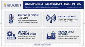
Wider temperature tolerance is the clearest signal. Standard commercial component ratings run 0°C to 70°C, while industrial-grade parts are commonly rated -40°C to 85°C, a range built to survive an unheated warehouse in January or a sealed control cabinet in July.
Beyond temperature, industrial boards need to withstand:
- EMI/EMC exposure — motors, relays, and variable-frequency drives generate electrical noise that can corrupt signals on nearby boards
- Continuous vibration and mechanical stress — from conveyor systems, pumps, and rotating machinery
- Chemical and dust exposure — common on factory floors and in outdoor enclosures
Component selection follows the same bar. Industrial designs use parts rated for wider temperature swings and built with regulatory protections in mind.
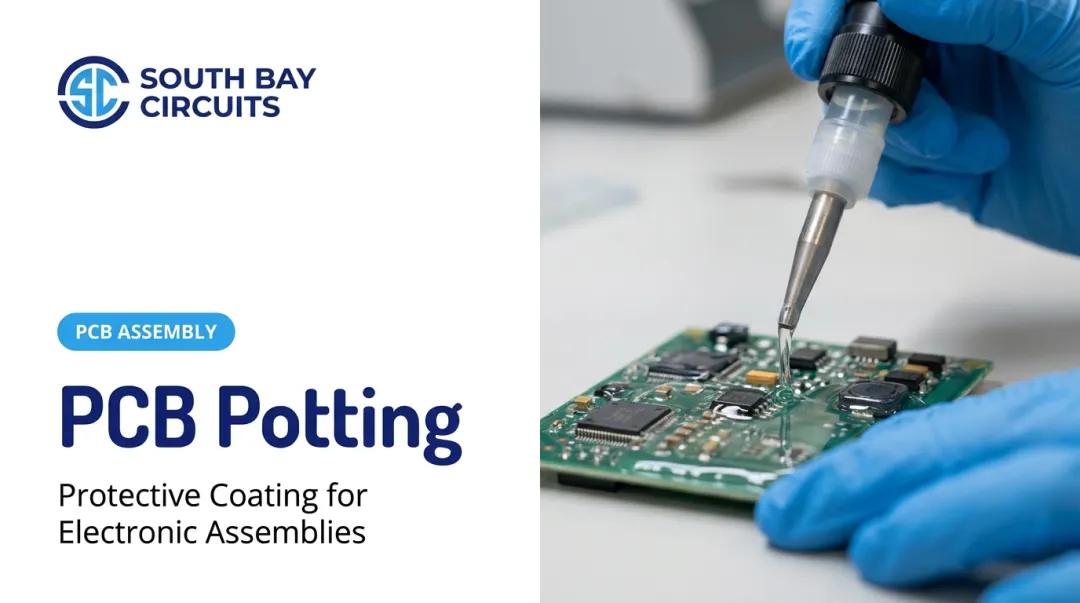
Repairability matters too. High-Tg laminates resist deformation during rework, so a technician can reflow a connector without warping the board. Conformal coating — typically silicone, acrylic, or urethane — adds environmental protection against moisture and chemical contaminants without sealing the board completely from future service.
Because the stakes are higher, manufacturers serving industrial customers are usually expected to hold a broader certification stack — ISO 9001, IATF 16949, AS9100, ISO 13485 — depending on the end market.
South Bay Circuits, for example, is ISO 9001:2015 certified and maintains quality systems aligned with AS9100, ISO 13485, and IATF 16949 requirements. That alignment supports work across aerospace, medical, and automotive customer bases.
Industrial PCB Design Rules Every Engineer Should Follow
Good industrial PCB design isn't guesswork. It follows established standards that account for current load, voltage, and heat.
Trace Width, Spacing & Current-Carrying Capacity
Trace width has to match the expected current load and copper weight, or you get excessive heat rise and, eventually, a burned trace. IPC-2221 and its more detailed companion, IPC-2152, provide the formulas, factoring in conductor thickness, board material, vias, and copper planes. Rather than eyeballing it, run your numbers through a trace-width and current-capacity calculator before finalizing layout.
Spacing matters just as much as width in higher-voltage industrial power sections. Per IPC-2221B guidance:
- Clearance requirements scale directly with operating voltage
- Sea-level installations use one set of spacing values; installations above 3,050 meters need wider clearances because thinner air reduces dielectric strength
- Uncoated external conductors need more spacing than conformal-coated ones
Skipping this step is how arcing and intermittent shorts happen six months after deployment, not during bench testing.
Thermal Management & Material Selection
Heat is the enemy of long-term reliability. Thermal vias, copper pours, and heavier copper weights all pull heat away from hot components and spread it across the board.
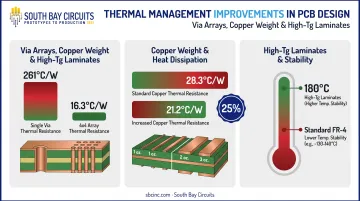
Texas Instruments found that a 4x4 array of thermal vias reduced thermal resistance from roughly 261°C/W for a single via down to about 16.3°C/W for the array when connected to multiple copper layers.
In a separate comparison, increasing bottom-layer copper weight cut junction-to-ambient thermal resistance from 28.3°C/W to 21.2°C/W — a 25% improvement, according to TI's thermal design application note.
For boards exposed to elevated ambient factory temperatures, high-Tg laminates matter. A laminate rated at Tg 180°C stays dimensionally stable well past the point where standard FR-4 starts to soften and warp. That stability is critical for boards that live near motor drives or in unventilated enclosures.
Component Placement, EMI/EMC & Design for Reliability
Layout decisions determine whether a board survives real-world electrical noise. Placement and EMI practices that hold up on the factory floor:
- Place decoupling capacitors close to power pins to suppress voltage transients
- Group like components together to simplify field servicing and reduce crosstalk
- Use grounding and shielding to isolate sensitive signal paths from noisy power sections
Reliability and serviceability details that prevent late failures:
- Route controlled-impedance traces where signal integrity is critical
- Size annular rings generously enough to survive drilling tolerance and thermal cycling
- Leave conformal-coating clearance zones around connectors and test points for rework
A board with perfect trace widths but poor grounding will still fail an EMC test near a variable-frequency drive.
Materials & Types of Industrial PCBs
Material choice should match the environment the board will actually live in — not just what's cheapest to order.
| Material | Best For | Key Trait |
|---|---|---|
| High-Tg FR-4 | General industrial control boards | Tg ~180°C, affordable, rework-friendly |
| Polyimide | Extreme heat, aerospace, downhole drilling | Tg up to 250°C, higher cost |
| Aluminum metal-core | LED lighting, motor drives, power supplies | High thermal conductivity (~7 W/m-K) |
| Heavy copper | High-current power electronics | 3 oz+ copper for current capacity and heat spreading |
High-Tg FR-4 and polyimide cover boards that need rework access plus thermal stability. FR-4 costs less and suits most industrial control work. Polyimide costs more but holds up under much higher sustained temperatures — common in engine controls and downhole equipment.
Metal-core and heavy copper boards focus on getting heat out fast:
- Aluminum-core boards put a thin dielectric between the copper circuit and an aluminum base that acts as a heat sink — common in industrial LED lighting and motor drives
- Heavy copper boards (3 oz or more per layer) carry high-current power supplies without overheating traces
Multilayer and HDI designs pack more components into less space for industrial control and networking. Boards with 20+ layers and blind/buried vias fit dense logic without growing the outline.
Rigid-flex boards tackle space and vibration together. They drop connector footprints, fold into tight housings, and hold up in sensors and robotics where a rigid board plus cable would fatigue and fail.
Applications of Industrial PCBs Across Key Industries
Industrial PCBs show up wherever electronics face heat, vibration, dust, or continuous duty cycles. The core reliability rules stay consistent, but each sector adds its own compliance bar and failure cost.
Industrial Automation & Process Control
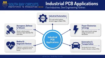
PLCs, sensor boards, and motor-drive controllers run 24/7 in dusty, vibration-heavy factory environments. These boards cannot afford downtime. A failed sensor board on a production line stops the whole process, not just one machine.
Power Electronics & Energy Systems
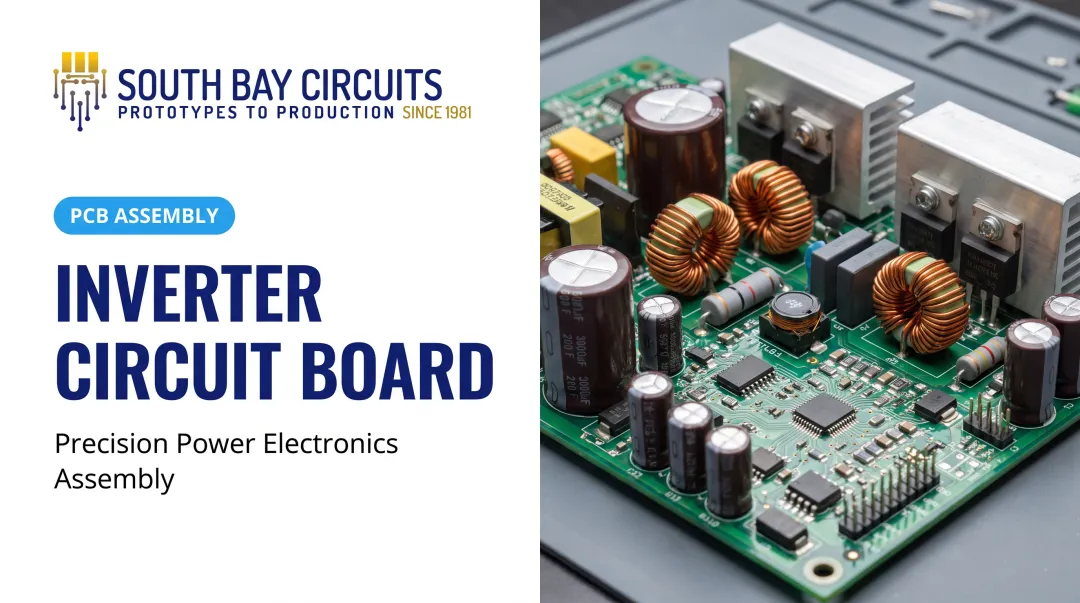
Switch-mode power supplies, DC-DC converters, and inverter boards operate under continuous electrical stress. They also need to tolerate soldering rework around protective fuses, since power components are the first thing to fail under overload.
Automotive & Transportation Electronics
Engine control units, safety systems, and infotainment boards face constant vibration and thermal cycling between a cold start and a hot engine bay. IATF 16949 compliance and PPAP documentation are baseline requirements in this market.
Medical & Diagnostic Devices
Patient-monitoring equipment and diagnostic instrumentation borrow industrial-grade reliability standards directly. ISO 13485 compliance, paired with FDA current good manufacturing practices under 21 CFR Part 820, governs design and manufacturing.
Aerospace, Defense & Telecommunications Infrastructure
Flight control systems, secure communications hardware, and network infrastructure boards have zero tolerance for field failure. EMI resistance and long-term dependability set the design requirements from the first layout pass.
High-reliability demand in this segment is still climbing. The radiation-hardened electronics market alone is projected to grow from $1.73 billion in 2024 to $2.42 billion by 2030, a 5.7% CAGR, according to Grand View Research. That trajectory mirrors broader investment in defense and aerospace electronics that must survive extreme environments.
Choosing the Right Industrial PCB Manufacturing Partner
Design rules only matter if your manufacturing partner can execute them consistently. That's where a lot of industrial projects stumble.
When you evaluate partners, prioritize verifiable process control, quality systems that match your industry, and turnaround that protects your NPI schedule—not unit price alone.
South Bay Circuits (SBC) has been building PCBs since 1981, with over 40 years of continuous operation from a 60,000+ square foot facility in Chandler, Arizona. As a single-source partner, SBC keeps design, fabrication, assembly, and box builds under one roof so your project is not handed off between vendors.
SBC's certification stack maps to the industries covered above:
- ISO 9001:2015 certified through UL-DQS (Certificate No. 10000903 QM15), covering fabrication, assembly, and box build
- AS9100-aligned quality systems for aerospace customers
- ISO 13485-aligned processes for medical device manufacturers
- IATF 16949-aligned systems for automotive OEMs
- ITAR registered and CMMC Level 1 compliant for defense work
Turnaround matters just as much on industrial programs. SBC offers 24-hour PCB fabrication and same-day assembly, with design-to-production transitions in as little as 48 hours. For teams on tight NPI schedules, that difference can cut weeks off a program timeline.
If you're planning your next industrial PCB project, contact SBC at sales@sbcinc.com or +1 480-940-3125 for a quote or design consultation.
Frequently Asked Questions
Is PCB manufacturing hard?
PCB manufacturing involves many precise chemical and mechanical steps, making it technically demanding to do well. Partnering with an experienced, certified manufacturer removes most of that complexity from the customer's side.
What's the difference between industrial and commercial PCBs?
Industrial PCBs handle wider operating temperatures (typically -40°C to 85°C versus 0°C to 70°C), use industrial-grade components, and require stronger EMI protection. They also typically demand more rigorous certification from the manufacturer.
What certifications should an industrial PCB manufacturer hold?
Look for ISO 9001 as a baseline quality certification, plus AS9100 for aerospace, ISO 13485 for medical devices, and IATF 16949 for automotive work. Together, they signal broad manufacturing readiness across regulated industries.
Which PCB material is best for high-temperature industrial environments?
High-Tg FR-4 handles most industrial applications affordably at up to roughly 180°C. Polyimide costs more but tolerates higher sustained heat, while metal-core boards excel when the priority is moving heat away from high-power components.
How long does industrial PCB fabrication and assembly typically take?
Timelines vary with design complexity and layer count, but expedited options exist. Some manufacturers offer 24-hour fabrication and same-day assembly, with standard production scheduled around specific project needs.
Can industrial PCBs be repaired after component failure?
Boards built with high-Tg materials and properly sized annular rings generally support rework and repair. Heavily conformal-coated or metal-core boards are harder to service since coating removal and heat dissipation complicate the process.