Engineers reference "reflow" constantly on manufacturing calls, but the actual zones, thermal profiles, and failure points behind it are often misunderstood at an operational level. A profile that works perfectly on one board design can produce tombstoning or voiding on the next.
This article covers what reflow soldering is, why manufacturers rely on it, how it works step by step, the variables that determine joint quality, and the mistakes that cause the most rework.
Key Takeaways
- Reflow soldering melts pre-applied solder paste in a controlled oven to permanently bond SMT components to PCB pads
- Standard method for surface-mount assembly, soldering hundreds of joints simultaneously with high repeatability
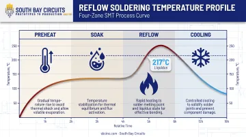
- The process runs through four thermal zones (preheat, soak, reflow, cooling), each with its own target and ramp rate
- Paste composition, stencil design, placement accuracy, and oven calibration drive joint quality more than any single factor
- Defects like tombstoning, voiding, and solder balling typically trace back to profile or paste-handling errors
What Is the Reflow Soldering Process?
Reflow soldering applies solder paste to PCB pads via stencil, places components onto that paste, then runs the assembly through an oven that melts the paste and forms a metallurgical bond between component leads and pads. Controlled cooling locks the joint in place.
A properly executed cycle produces void-free, mechanically strong joints that meet IPC acceptability criteria without overheating components or warping the board. Get the thermal profile wrong, and joints can look fine under a magnifying glass and still fail months later in the field.
Reflow vs. Wave Soldering
These two processes solve different problems, and confusing them at the design stage causes real cost issues later:
| Factor | Reflow Soldering | Wave Soldering |
|---|---|---|
| Component type | Surface-mount | Through-hole |
| Solder delivery | Pre-deposited paste | Molten solder wave |
| Best suited for | Fine-pitch, high-density boards | Bulk through-hole components |
You wouldn't wave-solder a 0.4mm BGA, and you generally wouldn't reflow a board full of heavy relays without a paste-in-hole workaround (more on that later).
Three Soldering Categories in Electronics Manufacturing
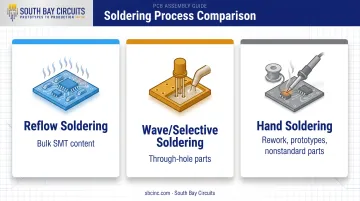
IPC's component-classification standard, IPC-9502, groups components into three broad process categories. Most production boards today use a mix of all three:
- Reflow for the bulk of surface-mount content
- Wave or selective soldering for through-hole parts
- Hand soldering for rework, prototypes, or nonstandard components that don't fit either automated process
Why Reflow Soldering Matters for Electronics Manufacturers
Reflow became the dominant assembly method because it's the only mass-soldering process that reliably handles high component density and fine-pitch packages. Alternatives fall short at scale:
- Wave soldering can't place solder precisely enough for a 0201 resistor or a fine-pitch BGA
- Hand soldering can handle fine pitch, but not at production volume with consistent results across thousands of boards
The stakes are real. An IPC-published case study on lead-free reflow profiling tracked one production line that recorded 38 solder-joint defects across 1,581 boards before correcting its reflow profile. The fix raised peak temperature by roughly 10°C and cut time above 183°C by about 5 seconds.
After the correction, the same line produced just 1 defective joint across 651 boards. That's the difference a properly tuned profile makes.
For OEMs evaluating a contract manufacturer, understanding reflow principles gives you a real yardstick for judging a partner's process control, not just their equipment list. South Bay Circuits runs reflow assembly across two in-house Fuji SMT lines paired with BTU VIP 70 and Conceptronic HVA-70 convection ovens, all under one roof at its Chandler, Arizona facility.
Keeping stencil printing, placement, and reflow on a single production floor removes the file transfers, shipping, and vendor handoffs that introduce delay between fabrication and assembly stages.
How the Reflow Soldering Process Works
The process starts with stencil printing: solder paste (a mix of metal alloy powder and flux) gets squeegeed through a stainless-steel stencil onto exposed PCB pads. Pick-and-place equipment then sets each component onto its wet paste deposit, using the paste's tackiness to hold parts in position until they're soldered.
From there, the board travels through a multi-zone oven on a conveyor, where a programmed thermal profile heats and cools it in sequence. Four inputs determine the outcome:
- The solder paste
- The stencil-printed board
- The placed components
- The programmed thermal profile
Independently controlled oven zones, conveyor speed, and thermocouple-based profiling (which measures actual board temperature against the target curve) give engineers the control needed to hit that profile consistently, board after board.
During the core transformation, the alloy reaches its melting (liquidus) point, flux activates to strip oxidation from the metal surfaces, and molten solder wets the pads and leads before solidifying. What comes out the other end is a board where paste has gone from soft metal powder to molten liquid to a solid, permanent connection.
Step 1: Preheat
The board enters the oven and warms gradually, avoiding thermal shock that can crack components or delaminate the board. Solvents in the paste begin evaporating during this stage. Push the ramp rate too fast and you risk solder balling or component damage; too slow, and you add unnecessary cycle time without benefit.
Step 2: Soak
Next, the oven holds the board at a steady temperature so every area — from small passives to dense BGA packages — reaches thermal equilibrium. Flux fully activates during soak, cleaning oxidation off pads and leads so solder can properly wet the metal in the next zone. Shorten soak too much, and uneven heating across the board shows up later as tombstoned components or inconsistent joints.
Step 3: Reflow
Oven temperature spikes above the alloy's liquidus point, melting the paste so it wets the pads and leads and forms the metallurgical bond. For a common lead-free SAC305 paste such as AIM's WS483, that means a peak of 230-245°C against a 217°C liquidus reference. Time above liquidus typically runs 30 to 90 seconds, depending on profile length. Too little time above liquidus and the joint doesn't wet properly; too much, and heat-sensitive components risk damage along with excess intermetallic growth.
Step 4: Cooling
The board then cools at a controlled rate to solidify joints with a fine, uniform grain structure. Cool too fast and joints can turn brittle; cool too slow and you get larger grain structures with weaker fatigue resistance. The right cooling rate depends on the specific paste and the assembly's thermal mass.
Where Reflow Fits in Production and What Drives Outcomes
Where Reflow Soldering Happens
Reflow shows up in several places across the assembly lifecycle, not just the main SMT line:
- Standard SMT production lines running high-volume boards
- Prototype and NPI builds, applying the same principles at smaller batch sizes
- Rework stations, using hot air or infrared tools for individual joint repairs
- Mixed-technology boards using intrusive (paste-in-hole) reflow for select through-hole parts
On a standard board, reflow occurs at a fixed point: after stencil printing and component placement, before inspection. It runs on every production cycle, every board, every time. Manufacturers that keep fabrication and assembly under one roof move a job through that sequence without the queue time added by shipping bare boards to a separate assembly house.
Key Factors That Influence Reflow Outcomes
Five variables do most of the work in determining whether a cycle produces a clean joint or a defect:
- Solder paste composition: alloy type, flux activity, and particle size affect melting behavior, wetting, and void formation
- Oven type and zone count: infrared, forced convection, and vapor-phase ovens transfer heat differently; convection remains the common choice for uniform control
- PCB and component design: pad symmetry, copper balancing, and component mass influence tombstoning and warping risk
- Production scale and throughput: target line speeds determine oven length, conveyor speed, and load factor
- Industry-specific quality requirements: IPC Class 3 work for medical, aerospace, or automotive customers tightens tolerances and inspection depth; IPC-7530 is the standard reference for thermal profile development
South Bay Circuits applies these controls through IPC-A-610 Class 2 or Class 3 inspection criteria, X-ray and AOI verification, and fine-pitch placement down to 0.4mm with engineering review. That discipline matters on BGA and micro-BGA work, where paste volume and pad design leave little margin for error.
Common Issues, Misconceptions, and When Reflow May Not Be Appropriate
Reflow has a reputation as a "set it and forget it" process once the oven's programmed. It isn't. Profiles need re-validation for every new board design, paste type, or component mix. Reusing an old profile on a new board is one of the most common causes of preventable defects.
There's also confusion between process and outcome. Running a board through a complete reflow cycle doesn't guarantee an acceptable joint. That's why inspection (visual, AOI, X-ray, or a mix depending on complexity) is a separate verification step, not an optional add-on.
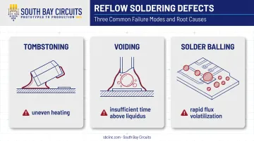
Another oversimplification: treating peak temperature as the only variable that matters. Ramp rates, soak duration, and time above liquidus play just as large a role in preventing:
- Tombstoning: a two-terminal component stands on end, usually from uneven heating between pads
- Voiding: gas pockets trapped inside a joint, often from too little time above liquidus or an excessive soak
- Solder balling: small solder spheres near joints, typically from rapid flux volatilization or an overly aggressive profile
When Reflow Isn't the Right Call
Reflow doesn't fit every job. It makes less sense for:
- Low-volume, through-hole-only boards, where wave or hand soldering is faster and cheaper
- Bulky or heavy components better suited to selective soldering
- Individual joint rework, where a hot air pencil beats running a whole board through an oven
If a design is mostly through-hole with just a handful of SMT parts, forcing a full reflow cycle can add cost and thermal risk without a real benefit over selective soldering. Flag that mix at the design stage, before tooling is committed.
Conclusion
Reflow soldering is a precisely controlled, four-zone thermal process that turns solder paste into permanent, reliable connections between components and the board. Getting it right means treating paste selection, oven profiling, and defect analysis as connected decisions, not separate checkboxes.
The difference between a merely functional process and a high-yield one usually comes down to one thing: a board-specific profile, validated for that exact paste, component mix, and design — not a default setting carried over from the last job.
Frequently Asked Questions
What is reflow soldering and how does it work?
Reflow soldering attaches SMT components to a PCB by heating pre-applied solder paste through four zones (preheat, soak, reflow, and cooling) until it melts and solidifies into a permanent joint.
What is the difference between reflow soldering and wave soldering?
Reflow uses pre-deposited paste and oven heat for surface-mount components, while wave soldering passes boards over molten solder for through-hole parts. Board design determines which process, or combination, applies.
What are the benefits of reflow soldering?
Reflow supports high-density, fine-pitch boards that wave or hand soldering can't handle reliably, and it solders hundreds of joints simultaneously in one pass. It's also far more repeatable and easier to automate than manual soldering at production volume.
What are the three types of soldering?
Electronics manufacturing generally uses reflow soldering for surface-mount parts, wave soldering for through-hole components, and hand or rework soldering for manual, low-volume, or repair work.
What temperature is used in reflow soldering?
Peak temperature depends on the alloy. Common lead-free SAC pastes typically peak around 230-245°C, with the exact figure and time-above-liquidus window set by the paste manufacturer's datasheet.
Can reflow soldering be used for through-hole components?
Yes, through a modified process called intrusive or paste-in-hole reflow, which fills holes with paste and solders them during the standard reflow cycle. It works within limits: component heat tolerance and paste volume both need qualification against standard wave soldering.