Introduction
Every PCB starts as a set of design files and a lot of assumptions. Prototype assembly is where those assumptions get tested against reality, and it's the single most effective checkpoint for catching problems before they become expensive.
Skip this step, or rush it, and the consequences show up later: board respins, blown deadlines, and product launches that stall because a design flaw made it all the way to volume production.
NASA's own systems engineering guidance makes the point directly: design changes get significantly more expensive the later they're discovered. Catching issues earlier keeps corrective action manageable.
This guide covers what prototype assembly actually involves, the four prototype types engineers work with, key design considerations, a step-by-step breakdown of the process, how to test and validate a build, and how to move into full production without starting over.
Key Takeaways
- Prototype assembly validates design, function, and manufacturability before committing to volume production
- Component lead times, DFM gaps, and signal integrity issues cause most prototype delays
- Four prototype types—proof-of-concept, visual, functional, and production-intent—map to distinct development goals
- AOI, continuity testing, and environmental stress testing catch defects before they reach the field
- Single-source manufacturing partners shorten the prototype-to-production handoff
What Is Prototype Assembly? Definition, Importance & Benefits
Prototype assembly is the process of building and testing a limited quantity of a physical PCB or product to confirm that the design works, performs as intended, and can be manufactured at scale.
It's the practical answer to "what is a prototype in manufacturing": a real, physical build used to find problems before they multiply across thousands of units.
The core purpose is straightforward. You're verifying that a design performs correctly under real operating conditions, not just on a schematic. That includes checking electrical function, mechanical fit, and whether the assembly process itself introduces defects.
Why Prototyping Pays Off
The benefits compound quickly:
- Risk reduction — problems surface while they're still cheap to fix
- Cost savings — avoiding a full production respin protects tooling investment and inventory
- Faster iteration — a working prototype gives engineers something concrete to test and refine
Faster iteration matters more than it first appears. Early discovery of design flaws is far less costly than late-stage correction. NASA's engineering handbook applies this principle across complex hardware programs, and it scales down to a single board just as easily.
Common Prototype Challenges
Prototype builds also come with friction:
- Component availability can stall a build before it starts
- Timelines are tight, especially for time-sensitive NPI schedules
- Per-unit costs run higher than production because fixed costs (tooling, setup, programming) get spread across far fewer boards
Higher per-unit cost is the structural difference between prototype and production assembly. Prototypes run in low volumes with minimal tooling investment. Full production amortizes non-recurring engineering, stencils, and line setup across thousands of units, so the same board costs noticeably less per unit once it scales.
The Four Main Types of Prototypes
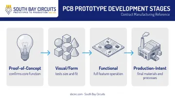
Not every prototype serves the same purpose. Product development uses four categories, each answering a different question at a different stage.
- Proof-of-concept — confirms the core function works, without worrying about final form or features
- Visual/form prototype — communicates size, shape, and physical viability, often without full electrical function
- Functional prototype — includes all intended features and operates like the finished product
- Production-intent prototype — built using production materials and processes, as close to final as possible before tooling commits
Matching Prototype Type to PCB Assembly Approach
These categories map onto real PCB assembly decisions:
- PTH (plated through-hole) works well for early proof-of-concept builds where speed and rework flexibility matter more than density
- SMT suits functional and production-intent prototypes that need to mirror final board performance
- Hybrid assembly combines SMT and through-hole on the same board when a design mixes fine-pitch components with connectors or power parts that need through-hole strength
A concrete example is a functional PCB prototype for a sensor module that combines analog signal-conditioning circuitry with a microcontroller. SBC's design team can support both the sensor-side analog layout and the digital control circuitry, then carry the board into fabrication and assembly without a handoff to another vendor.
Critical Design Considerations Before Assembly
Good prototypes are won or lost at the design stage. A handful of decisions here determine whether the build goes smoothly or stalls.
Component Selection and Availability
Choose standard, easily sourced parts wherever possible. Exotic or single-source components introduce schedule risk that's hard to recover from mid-project.
Component lead times remain volatile. According to UltraLibrarian's 2025 lead-time report, mid-2025 averages were:
- 34 weeks for passives
- 31 weeks for sensors
- 26 weeks for discretes
- 18 weeks for interconnects
Identifying long-lead parts during schematic development—not after layout—is the difference between an on-schedule prototype and a delayed one.
DFM and DFA Guidelines
Design for Manufacturability (DFM) and Design for Assembly (DFA) reviews catch problems before they become physical defects:
- Trace-and-space specs that exceed standard fabrication capability
- Component footprints that invite tombstoning or bridging during reflow
- Insufficient clearance for automated placement equipment
Signal Integrity, Thermal Management, and Stack-Up
Three design choices decide whether a prototype survives first power-on and scales cleanly into production:
- Signal integrity: On high-speed designs, controlled impedance and careful trace routing aren't optional. IPC-2141 guides controlled-impedance board design; get the stack-up right the first time to avoid a redesign.
- Thermal management: On dense boards, thermal vias and heat sinks move heat away from hot components before it becomes a reliability problem.
- Production-ready stack-up: Choose a layer stack-up with volume builds in mind, not just prototype convenience. That choice makes scaling far less disruptive later.
The Prototype Assembly Process: A Step-by-Step Breakdown
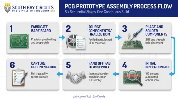
Here's how a prototype actually moves from files to a working board.
- Fabricate the bare board. Gerber files go to fabrication, typically using FR-4. Quick-turn fabrication can run in as little as 24 hours; standard timelines run longer depending on layer count and materials.
- Source components and finalize the BOM. This happens while the board is in fabrication, not after. A complete BOM with designators, manufacturer part numbers, and AVL data prevents costly delays once assembly starts.
- Place and solder components. SMT reflow handles fine-pitch and BGA parts efficiently; through-hole soldering (wave or hand) suits connectors and power components. Mixed-technology boards use both.
- Run initial inspection. Visual checks and Automated Optical Inspection catch solder defects (bridges, insufficient solder, cold joints) before the board goes any further.
- Hand off fab to assembly without delay. When design, fabrication, and assembly sit under one roof, you skip shipping time and vendor queues. At SBC's Chandler, Arizona facility, fabrication can finish in as little as 24 hours and assembly can start the same day.
- Capture documentation. Traceability records, inspection data, and updated BOMs create the baseline that makes the handoff into production smoother later.
Testing and Validating Your Prototype
A clean-looking board can still fail under load. Validation works in layers, from pre-power checks through stress conditions that match the end environment.
Before power ever touches the board, visual inspection and continuity testing catch physical defects (opens, shorts, misaligned components) that would otherwise damage the board or mask a real functional problem.
Functional testing then confirms the board performs its intended job under expected voltage and current. Analog and digital functional testers, plus in-circuit checks for resistance and capacitance, verify behavior beyond basic continuity.
Demanding industries need more than a functional pass:
- Aerospace and defense rely on standards like MIL-STD-810H for environmental tailoring and lab test methods
- Automotive applications reference ISO 16750 for electrical, mechanical, and climatic load testing
- Medical devices follow IEC 60601-1 for basic safety and performance
Solder-joint fatigue testing under thermal cycling (IPC-9701B) is another layer worth applying to any board headed for a harsh operating environment.
From Prototype to Full Production: Choosing the Right Partner
Not every manufacturer that builds a good prototype can scale it into production without friction. A few things separate the ones that can from the ones that can't.
What to evaluate in a manufacturing partner:
- Industry certifications: ISO 9001, AS9100 (aerospace), ISO 13485 (medical), IATF/TS 16949 (automotive)
- Turnaround speed at both prototype and production volumes
- True single-source capability: design, fabrication, assembly, and test under one roof
The reason a seamless transition matters isn't abstract. Switching vendors between prototype and production usually means re-qualification: new audits, sample builds, and documentation review. When something goes wrong, ownership gets fuzzy. A single-source model removes that ambiguity.
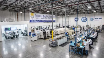
South Bay Circuits has run that single-source model for over 40 years from a 60,000+ square foot facility in Chandler, Arizona. Design, fabrication, assembly, and box builds stay in-house, so projects are not handed off between separate vendors.
SBC holds ISO 9001:2015 certification and works to AS9100, ISO 13485, and ISO/TS 16949 requirements for aerospace, medical, automotive, and industrial customers. Tooling, stencils, and testing are typically paid for once rather than re-charged at every stage from prototype through high-volume production.
Frequently Asked Questions
What is a prototype in manufacturing?
A manufacturing prototype is an early, limited-run physical build used to validate a design's function, performance, and manufacturability before committing to full-scale production. It's the real-world test that schematics alone can't provide.
What are the four types of prototypes?
The four commonly recognized types are:
- Proof-of-concept — tests core function
- Visual/form — tests shape and fit
- Functional — tests full operation
- Production-intent — built with final materials and processes
Each serves a different stage of development.
What is an example of a prototype?
A common example is a functional PCB prototype for a sensor or control board, built and tested for real-world performance before committing to a production run. It confirms both electrical function and assembly quality.
How long does PCB prototype assembly typically take?
Timelines vary with board complexity and component availability, but quick-turn services can fabricate and assemble a board in as little as 24-48 hours. Without quick-turn, standard builds often take several days to a few weeks.
What is the difference between prototype assembly and full production assembly?
Prototype assembly runs low volumes with minimal tooling and higher per-unit cost, while production assembly spreads fixed costs across thousands of units at optimized, repeatable processes. Production also applies more rigorous process control once the design is validated.
How much does prototype PCB assembly cost?
Per-unit costs run higher for prototypes because tooling, setup, and engineering time get spread across far fewer boards than a production run. That added upfront investment is what prevents far costlier redesigns after full production has already started.